
Malibu V6-191 3.1L VIN M SFI (1997)
stops. This procedure will position the pistons very close to the top of the hydraulic modulator bore, simplifying the brake bleeding procedure.
4. Position motor pack onto hydraulic modulator, aligning the three. motor pack gears with the modulator. Take care in handling the motor pack. If
dropped or damaged during handling, the motor pack must be replaced.
5. Motor pack to hydraulic modulator screws. Tighten screws to 5 Nm (44 inch lbs.).
6. Gear cover onto hydraulic modulator with screws. Tighten screws to 4 Nm (36 inch lbs.).
7. Hydraulic modulator into vehicle.
8. Perform Diagnostic System Check. See: Antilock Brakes / Traction Control Systems/Testing and Inspection
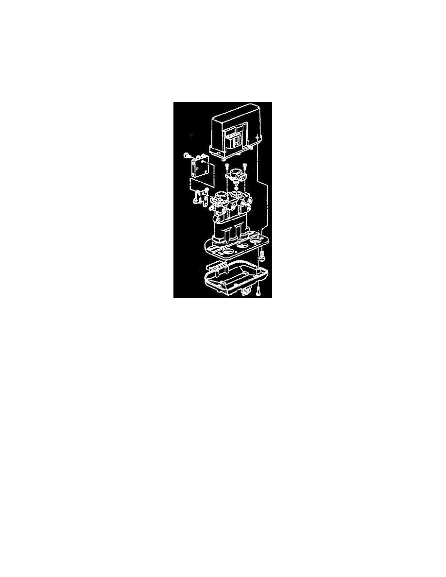
Hydraulic Modulator
DISASSEMBLE
1. Hydraulic modulator assembly.
2. Screws attaching gear cover.
3. Remove gear cover.
4. Screws attaching motor pack to hydraulic modulator.
5. Remove motor pack.
6. Proportioning valve mounting screws.
7. Remove Proportioning valve.
NOTE: If hydraulic modulator is to be replaced, install the three gears in the same location on replacement hydraulic modulator. No repair of the
hydraulic modulator is authorized. Replace as an assembly.
ASSEMBLE
1. Proportioning Valve to Hydraulic Modulator. Tighten Proportioning Valve screws to 12 Nm (106 inch lbs.). A new gasket MUST be used when
installing the Proportioning Valve.
2. With the hydraulic modulator upside down, and the gears facing you, rotate each hydraulic modulator gear counterclockwise until movement
stops. This procedure will position the pistons very close to the top of the hydraulic modulator bore.
3. Motor pack to hydraulic modulator assembly.
4. Motor pack to hydraulic modulator screws. Tighten Motor pack to hydraulic modulator screws to 5 Nm (44 inch lbs.).
5. Gear cover to hydraulic modulator assembly. If the gear cover seal is damaged, the cover must be replaced. Tighten Gear cover screws to 4 Nm
(36 inch lbs.).
6. Hydraulic modulator into vehicle.
7. Perform Diagnostic System Check. See: Antilock Brakes / Traction Control Systems/Testing and Inspection
Hydraulic Modulator Assembly Replacement
WARNING: To help avoid personal injury due to a retained load on the hydraulic modulator, the GEAR TENSION RELIEF function of the
scan tool must be performed prior to removal of the ABS hydraulic modulator assembly.
REMOVE OR DISCONNECT
1. Using the scan tool, perform GEAR TENSION RELIEF function under SPECIAL FUNCTIONS.