
Malibu V6-191 3.1L VIN M SFI (1997)
Installing Pulley Rotor And Bearing Assembly
Install or Connect
1. Place the pulley rotor on the J 21352-A support block to fully support the rotor hub during bearing installation.
NOTICE: Do Not support the rotor by resting the pulley rim on a flat surface during the bearing installation or the rotor face will be bent.
2. Align the new bearing squarely with the hub bore and using puller and bearing installer J 9481-A with universal handle J 29886, drive the bearing
fully into the hub. The installer will apply force to the outer race of the bearing if used as shown.
3. Place bearing staking guide J 33019-1 and bearing staking pin J 33019 in the hub bore as shown in the illustration. Shift the rotor and bearing
assembly on the J 21352-A support block to give full support of the hub under the staking pin location. A heavy-duty rubber band may be used to
hold the stake pin in the guide, and the stake pin should be properly positioned in the guide after each impact on the pin.
4. Using care to prevent personal injury. strike the staking pin with a hammer until a metal stake, similar to the original, is formed down to but not
touching the bearing.
The stake metal should not contact the outer face of the bearing to prevent the possibility of distorting the outer race. Stake three (3) places 120°
apart as shown in the illustration.
5. With the compressor mounted to the J 34992 holding fixture, position the rotor and bearing assembly on the front head.
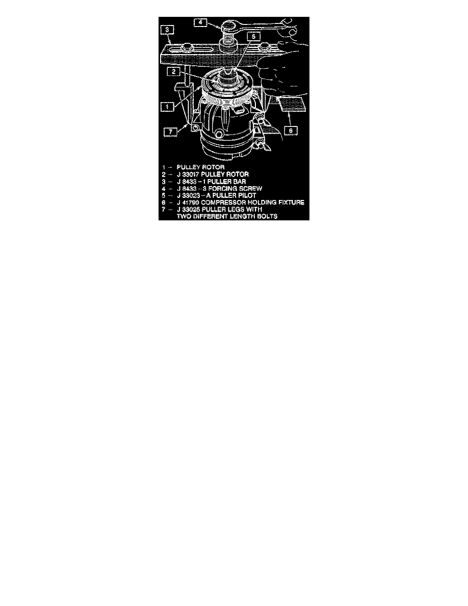
6. Position the J 33017 pulley rotor and bearing installer and J 33023-A puller pilot directly over the inner race of the bearing.
7. Position puller crossbar J 8433-1 on the puller pilot J 33023-A and assemble the two through bolts and washers through the puller bar slots and
thread them into the J 33025 puller leg. The thread of the through bolts should engage the full thickness of the puller legs. The two puller legs
require two different bolt lengths.
8. Tighten the center screw in the J 8433-1 puller crossbar to force the pulley rotor and bearing assembly onto the compressor front head. Should the
J 33017 pulley rotor and bearing installer slip off direct in-line contact with the inner face of the bearing, loosen the J 8433-3 center forcing screw
and realign the installer and pilot so that the J 33017 installer will properly clear the front head.
9. Install rotor and bearing assembly retainer ring, using snap ring pliers J 6083.
10. Reinstall clutch plate and hub assembly as described previously.