
Malibu V6-191 3.1L VIN M SFI (1997)
Body Control Module: Initial Inspection and Diagnostic Overview
Basic Knowledge Required
Before performing diagnosis there are some areas that you must be familiar with. Without this basic knowledge, you will have difficulty using diagnostic
procedures.
1. Basic Electrical Circuits - The basic theory of electricity is essential. An understanding of voltage, current, resistance and their relationships to
each other will help in the diagnosis of an open or shorted circuit. You must be able to read and understand a schematic wiring diagram.
2. Use of Circuit Testing Tools - You must know how to use jumper wires to bypass components to test circuits. You must be familiar with the High
Impedance Multimeter (DMM - Digital Multi Meter), particularly essential tool J 39200 or equivalent. You must be able to measure voltage,
resistance, and current with the DMM you are using.
3. Use of the scan tool - You must know how to use, connect, manipulate and diagnose circuits using this essential tool. You must be familiar with
screens and control module partitions.
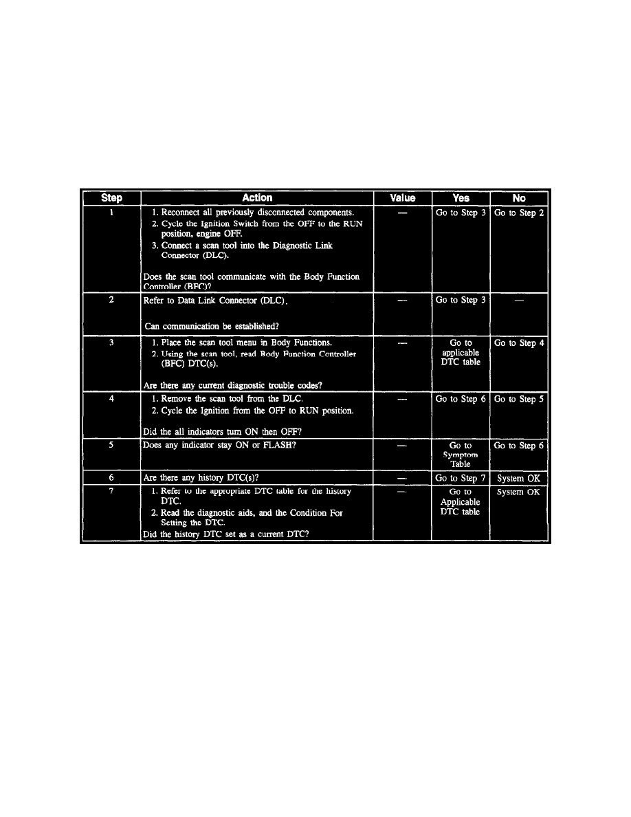
Body Function Controller System Check
Diagnostic Trouble Codes Warning
IMPORTANT
Do NOT replace the Body Function Controller (BFC) unless a Diagnostic Trouble Code (DTC) remains Current after all DTC tables have been
executed. NEVER replace the Body Function Controller (BFC) based on History codes.
The Body Function Controller (BFC) and the Electronic Brake Control Module (EBCM) are connected to the Class 2 serial data link and are capable of
setting Diagnostic Trouble Codes. The history DTC codes (a history DTC is a current DTC fault that disappears in the next ignition cycle) can be
especially useful in diagnosing an intermittent problem. An explanation of these are given below in Diagnostic Trouble Codes (DTC) TABLE #13.
On Vehicle Diagnostic Capabilities
Aboard this vehicle are electronic components which can be controlled by the service technician to provide valuable self-diagnostic information. These
components are part of an electrical network designed to control various engine and body subsystems.
System sensors and switches are monitored by the computer system. These components are
^
Body Function Controller (BFC)
^
Electronic Brake Control Module (EBCM)
^
Instrument Cluster