
Malibu V6-191 3.1L VIN M SFI (1997)
REMOVE OR DISCONNECT
1. Raise vehicle and suitably support. Allow front suspension to hang free.
2. Front tire and wheel assemblies.
3. Stabilizer links at control arm.
4. Tie rods from knuckle.
5. Rear engine mount bracket bolts, refer to Crossmember.
6. Rear crossmember bolts.
7. Loosen front crossmember bolts.
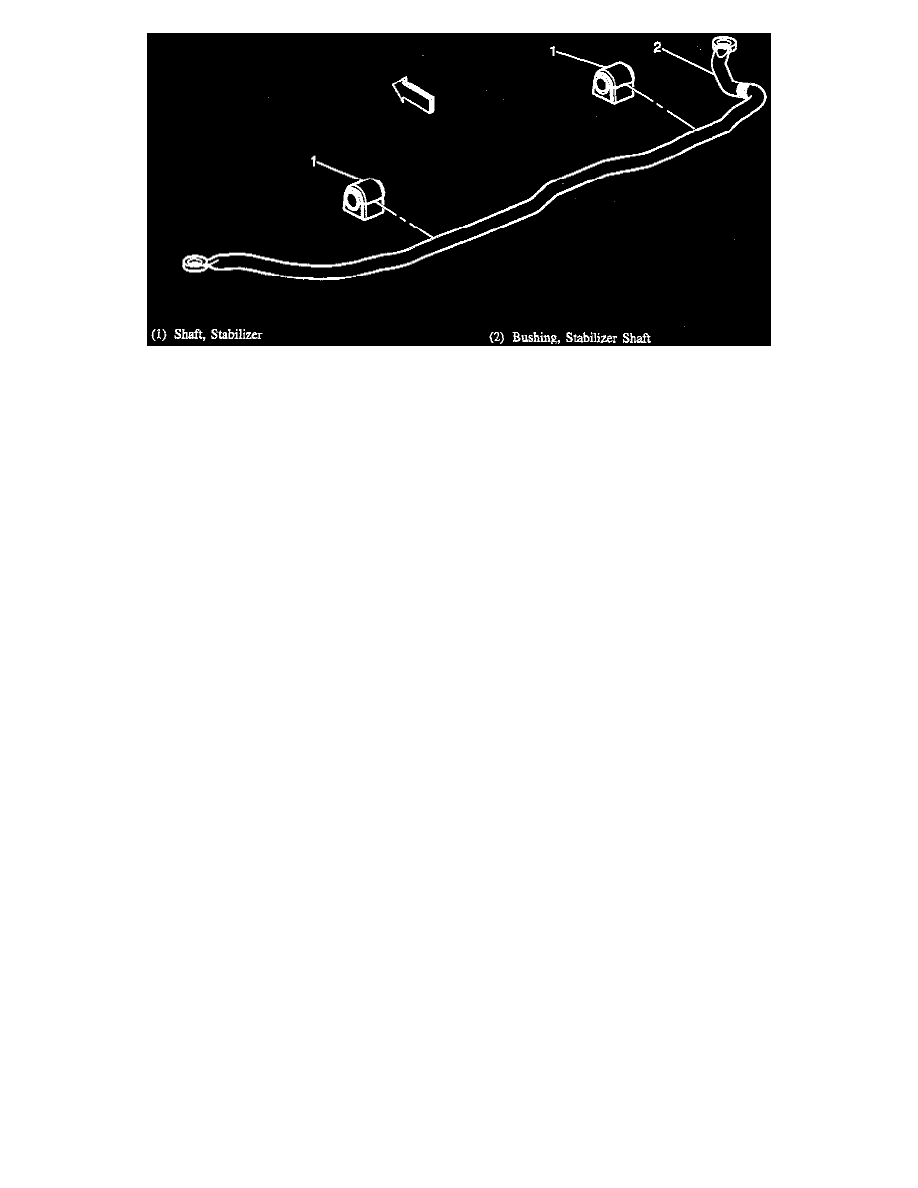
8. Clamps attaching stabilizer shaft to crossmember assemblies.
9. Stabilizer shaft bushings.
INSTALL OR CONNECT
1. Stabilizer shaft bushings.
2. Clamps attaching stabilizer shaft to crossmember assemblies (hand tighten).
3. Crossmember assemblies into position and install bolts (hand tighten).
4. Tighten crossmember bolts left rear outboard first, right rear outboard second, front upper third, rear inboard last to specifications.
^
Tighten:
-
Left rear outboard bolt, first to 110 Nm (71 ft lb) plus 90° rotation.
-
Right rear outboard bolt, second to 110 Nm (71 ft lb) plus 90° rotation.
-
Front upper bolts third to 110 Nm (71 ft lb) plus 90° rotation.
-
Rear inboard bolts last to 110 Nm (71 ft lb) plus 90° rotation.
5. Tighten clamp bolts to crossmember to specifications.
^
Tighten stabilizer shaft bushing clamp to support assembly bolts to 66 Nm (49 ft lb).
6. Tighten stabilizer links to control arm.
^
Tighten stabilizer shaft links to control arm nuts to 17 Nm (13 ft lb).
7. Tie rods to knuckle.
8. Rear engine mount bracket bolts, refer to Crossmember.
9. Front wheel and tire assemblies.