
Malibu V6-3.5L VIN 8 (2004)
Ignition Coil Pack: Customer Interest
Electrical - Loss Of Steering Assist/DTC C0900
TECHNICAL
Bulletin No.: 08-02-32-005A
Date: June 07, 2010
Subject: Loss of Power Steering Assist, Power Steering Warning Message Displayed in DIC, IPC/Radio Displays Erratic, DTC C0900, B1325 Set
(Replace Ignition Coil/Module Assembly and Add Ground Strap)
Models:
2004-2007 Chevrolet Malibu, Malibu Maxx
with 3.5L Engine (VINs 8, N - RPOs LX9, LZ4)
Supercede:
This bulletin is being revised to add the 2007 model year. Please discard Corporate Bulletin Number 08-02-32-005 (Section 02 - Steering).
Condition
Some customers may comment on a loss of power steering assist at high RPM (above 3500 RPM) and a power steering warning message displayed in the
DIC. They may also comment some instrument/radio displays are erratic.
Upon investigation, the technician may find DTC C0900 set. If the displays were erratic, then DTC B1325 will also be set.
Cause
This condition may occur when the system voltage exceeds 16 volts for one second for code C0900 and the system shuts down to protect it from
over-voltage operation. If the voltage exceeds 18 volts for five seconds for code B1325, then other electronic systems protect themselves and shut down.
It has been found that this voltage increase is caused by an interaction between the alternator and the ignition coil/module assembly.
Correction
Replace the ignition coil/module assembly and add ground strap following the procedure below.
1. Disconnect the ignition coil electrical connector.
2. Disconnect the left side spark plug wires from the ignition coil.
3. Disconnect the right side spark plug wires from the ignition coil.
4. Remove the four bolts attaching the ignition coil to its mounting bracket and remove the ignition coil.
5. Remove the ignition coil from the mounting bracket.
6. Loosen the two lower ignition coil mounting bracket nuts.
7. Remove the two upper ignition coil mounting bracket bolts and discard.
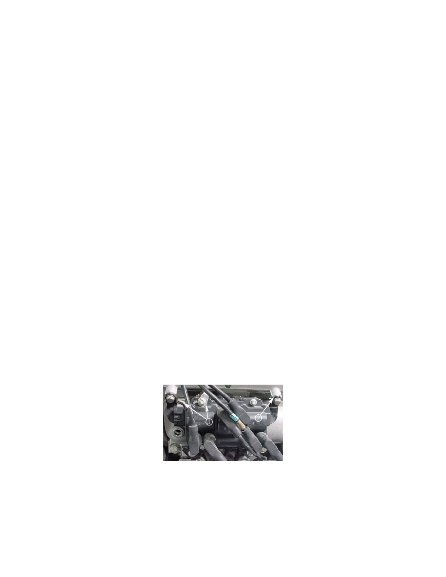
8. Install the ground strap (1), P/N 12581176, to the upper left side of the bracket as shown between the coil bracket and intake. Install the new
bracket bolt, P/N 11570082, (do not tighten at this time). Prior to installing the ground strap, remove the captured nut and washers. They are not
needed (simply pound them out with a hammer on a vise).
Install the washer (2), P/N 02436162, to the upper right side of the bracket between the coil bracket and intake. Install the new bracket bolt, P/N
11570082, (do not tighten at this time).
Tighten
Tighten all the ignition coil bracket bolts and nuts to 25 Nm (15 lb ft).
9. Install the new ignition coil to the mounting bracket.