
Malibu V6-3.5L VIN 8 (2004)
1. Separate the connector halves (1).
2. Open the secondary lock. A secondary lock aids in terminal retention and is usually molded to the connector (1).
3. Grasp the wire and push the terminal to the forward most position. Hold the wire in this position.
4. Insert the Weather Pack(R) terminal removal tool into the front (mating end) of the connector cavity until it rests on the cavity shoulder (1).
5. Gently pull on the wire to remove the terminal through the back of the connector (2).
IMPORTANT: Never use force to remove a terminal from a connector.
6. Inspect the terminal and connector for damage - Repair as necessary.
7. Reform the lock tang (2) and reset terminal in connector body.
8. Close secondary locks and join connector halves.
9. Verify that circuit is complete and working satisfactorily.
10. Perform system check.
Micro-Pack 100W Connectors
MICRO-PACK 100W CONNECTORS
TOOLS REQUIRED
J 38125-D Terminal Repair Kit
REMOVAL PROCEDURE
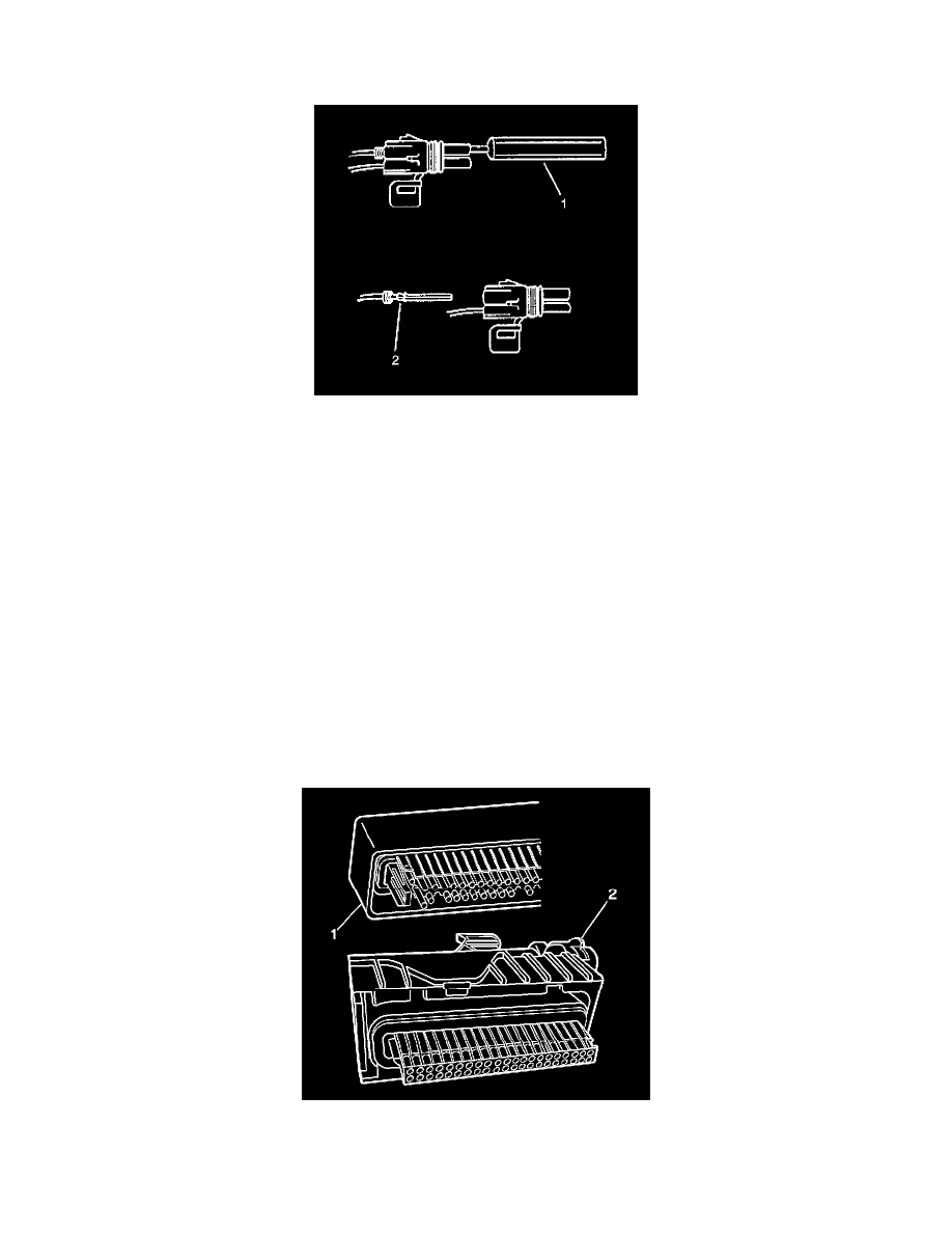
There are 2 styles of Micro-Pack 100W connectors. These connectors are very similar but use different terminals and have some minor physical
differences also.
The first connector design of the Micro-Pack 100W (1) has a white connector interface that holds the terminals. The second design of the Micro-Pack
100W (2)has a gray interface to hold the terminals. Also, the first design has terminal cavities that are further apart (3 mm centerline) and offset from
the other row of terminal cavities in the connector. The second design has terminals cavities that are closer together (2.54 mm centerline) and aligned
vertically. One other way to identify the second design is the thin strip of material that runs along the outside of the cavities.