
Malibu V6-3.9L (2007)
Important:
^
Do NOT install used correction plates in an attempt to correct brake rotor assembled LRO.
^
Do NOT stack up, or install more than one correction plate onto one hub/axle flange location, in an attempt to correct brake rotor
assembled LRO.
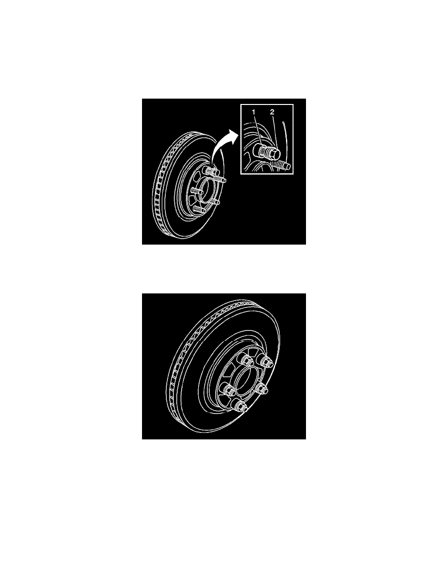
Install the correction plate (1) onto the hub/axle flange, with the V-shaped notch (2) orientated to align with the high spot mark (3), that was
positioned to face upward.
6. Install the brake rotor to the hub/axle flange. Use the matchmark made prior to removal for proper orientation to the flange.
7. Hold the rotor firmly in place against the hub/axle flange and install one of the J 45101-100 (1) and one lug nut (2) onto the upper-most wheel
stud.
8. Continue to hold the rotor secure and tighten the lug nut firmly by hand.
9. Install the remaining J 45101-100 and lug nuts onto the wheel studs and tighten the nuts firmly by hand in a star-pattern.
10. Using the J 39544-KIT, or equivalent, tighten the lug nuts in a star-pattern to specification, in order to properly secure the rotor.
11. Measure the assembled LRO of the brake rotor. Refer to Brake Rotor Assembled Lateral Runout Measurement.
12. If the brake rotor assembled LRO measurement still exceeds the maximum allowable specification, refer to Brake Rotor Assembled Lateral
Runout Correction.
13. If the brake rotor assembled LRO measurement is within specification, install the brake caliper and depress the brake pedal several times to secure
the rotor in place before removing the J 45101-100 and the lug nuts.