
Metro L3-061 1.0L VIN 6 TBI (1998)
INSTALLATION PROCEDURE
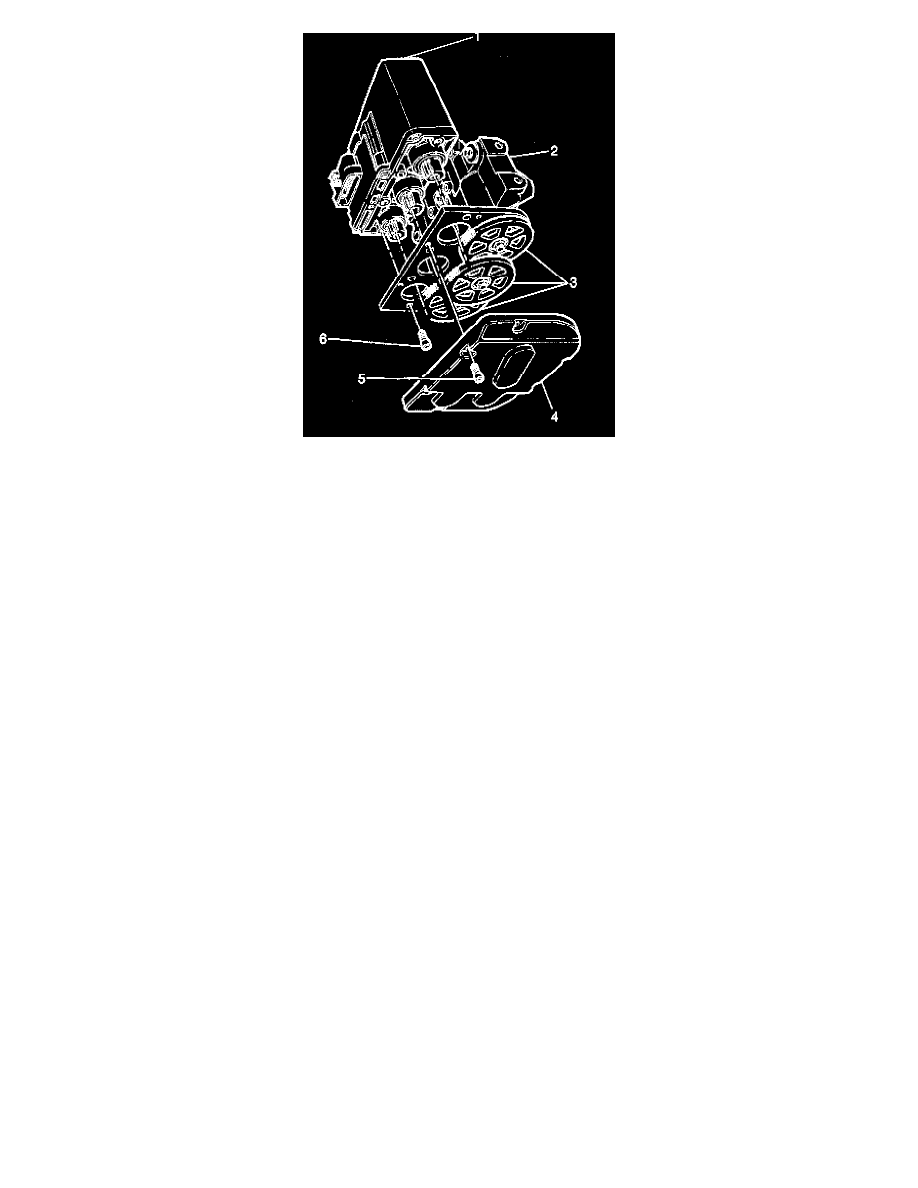
1. Position the modulator drive gears (3) onto the modulator drive shaft.
2. Install the three gear retaining nuts.
^
Tighten the nuts to 8.5 Nm (76 inch lbs.).
NOTICE: Refer to Service Precautions.
3. With either of the modulators positioned upside down, and the gears facing your, rotate each ABS brake modulator gear counterclockwise until
movement stops.
Rotating the modulator gears will cause the following conditions:
^
The pistons on the ABS brake modulator will be positioned very close to the top of the modulator bore.
^
The brake bleeding procedure is simplified.
IMPORTANT: Use care when handling the motor pack. Replace the motor pack if the motor pack is dropped or damaged during handling.
4. Position the motor pack (1) onto the modulator (2), aligning the three motor pack gears with the modulator gears (3).
5. Install the four motor pack to modulator Torx head screws (6).
^
Tighten the four Torx head screws (6) to 5 Nm (44 inch lbs.).
6. Install the gear cover (4) onto the modulator (2) with the six Torx head screws (5).
^
Tighten the six Torx head screws (5) to 4 Nm (36 lb in).
7. Install the Hydraulic Modulator assembly into the vehicle.
8. Perform the Motor Rehome Procedure.
9. Perform the "Diagnostic System Check".