
Metro L3-061 1.0L VIN 6 TBI (1998)
Idle Speed: Testing and Inspection
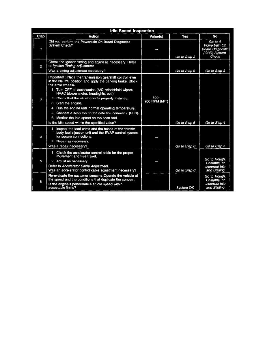
Idle Speed Inspection
Idle Speed Inspection
Notice: Do not manually adjust the engine idle. Damage to the Idle Speed Control (ISC) system may occur.
If the engine idle speed is outside of the specifications, inspect the ISC system for the proper operation.
The engine idle speed is controlled by the powertrain control module (PCM) through the idle speed control (ISC) motor. The ISC motor opens and
closes the throttle valve according to signals from the PCM. The PCM determines the correct engine idle speed by using information from various
sensors and switches. The PCM increases ISC duty (increases throttle valve opening) when engine speed drops below a specified value. The PCM
maintains a smooth and stable idle by monitoring certain engine components in order to respond to changes in engine load. The engine idle speed is
preset at the factory and is not adjustable.
Diagnostic Aids
Check the A/C Idle-Up circuit if the engine idle speed is a concern when the air conditioning or windshield defroster are running. Refer to A/C Idle
Circuit Diagnosis.
Check the Electrical Load Idle-Up Signal circuit if the engine idle speed is a concern when the headlights, blower motor, or rear defogger are on. Refer
to Electrical Load Idle-Up Signal Diagnosis.
The engine ISC motor and idle speed (throttle opening) are not adjustable. DO NOT attempt to adjust the ISC motor, the throttle stop screw, or the
throttle lever screw. Operate the ISC motor with the scan tool by selecting the appropriate Output Control feature. Command the ISC motor to increase
and decrease engine idle speed. Diagnose and replace the faulty component or locate and repair the cause of the idle concern.
Test Description
The numbers below refer to the step numbers in the Diagnostic Table.
1. The Powertrain OBD system check prompts the technician to complete some basic checks and store the Freeze Frame data on the scan tool if
applicable. This creates an electronic copy of the data taken when the fault occurred. The information is then stored in the scan tool for later
reference.