
Metro L3-061 1.0L VIN 6 TBI (1998)
System Description
The powertrain control module (PCM) will energize the fuel pump relay for 2 seconds when the ignition switch is turned to the ON position. The fuel
pump will operate and pressurize the fuel system when the fuel pump relay is energized. The PCM receives ignition system reference pulses when the
engine is being cranked or when the engine is running. The PCM will continue to energize the fuel pump relay as long as the PCM receives ignition
system reference pulses. The PCM will de-energize the fuel pump relay when ignition system reference pulses are no longer detected.
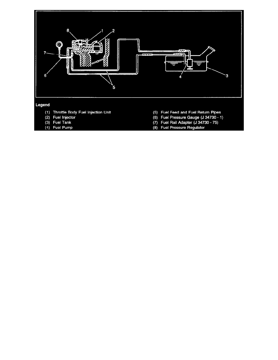
The fuel pump will deliver fuel to the fuel injector in the TBI unit at a controlled pressure. The controlled pressure is 160-210 kPa (23-31 psi) when the
fuel pump is energized and the engine not running. The controlled pressure is 90-140 kPa (13-20 psi). when the engine is idling at normal operating
temperatures. The fuel pressure regulator maintains the correct fuel pressure at all times by returning excess fuel to the fuel tank.
Diagnostic Aids
Improper fuel system pressure can result in any of the following conditions:
^
The engine cranks but will not start.
^
The engine cuts out or stalls (may feel like an ignition malfunction).
^
A decrease in fuel economy and a loss of power.
^
Hard starting.
Check for water contamination of the fuel if the vehicle won't start in freezing weather. Ice can form in the fuel system and prevent the fuel from reaching
the fuel injectors at the necessary fuel pressure and volume.
Normal fuel pump electrical resistance is 0.8-1.5 ohms at 20°C (68°F).
An intermittent malfunction may be caused by a problem in the fuel pump electrical circuit. Inspect the wiring harness and components for any of the
following conditions:
^
Backed out terminals.
^
Improper mating of terminals.
^
Broken electrical connector locks.
^
Improperly formed or damaged terminals.
^
Faulty terminal to wire connections.
^
Physical damage to the wiring harness.
^
A broken wire inside the insulation.
^
Corrosion of electrical connections, splices, or terminals.
Test Description
The numbers below refer to the step numbers in the Diagnostic Table.
1. The Powertrain OBD System Check prompts the technician to complete some basic checks and store the freeze frame data on the scan tool if
applicable. This creates an electronic copy of the data taken when the fault occurred. The information is then stored in the scan tool for later
reference.