
Metro L3-061 1.0L VIN 6 TBI (1998)
Throttle Position Sensor: Adjustments
TP Adjustment Using A Digital Multimeter
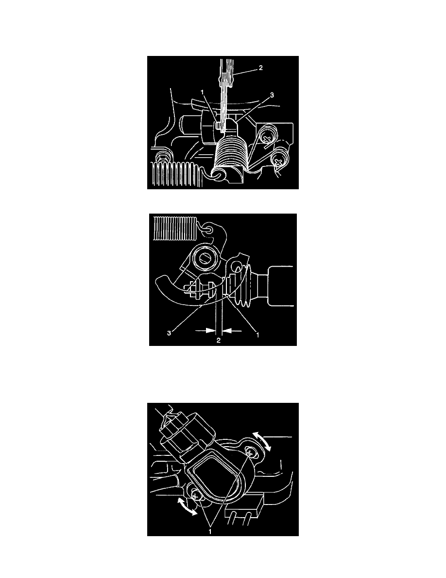
1. Remove the air cleaner (if necessary). Refer to Air Cleaner Assembly Replacement.
2. Insert a 3.5 mm (0.14 in.) feeler gage (2) between the throttle stop screw (1) and the throttle lever (3).
3. Inspect the idle speed control (ISC) motor plunger. If the ISC motor plunger (1) is contacting the throttle lever screw (3), then the engine must be
brought to operating temperature. There must be no contact (2) between the ISC motor plunger and the throttle lever screw.
4. Back probe the throttle position (TP) sensor signal circuit at the powertrain control module electrical connector to ground.
5. Turn ON the ignition.
6. Observe the TP sensor voltage on the DMM. The TP sensor voltage reading should be 0.98 to 1.02 volts.
7. If the TP sensor voltage IS NOT 0.98 to 1.02 volts, loosen the TP sensor screws (1) and turn the TP sensor until the voltage reading is 0.98 to 1.02