
Metro L3-061 1.0L VIN 6 TBI (1998)
Engine Control Module: Service and Repair
PCM Replacement Procedure
Notice: Check the resistance values of all PCM relays, solenoids, and other output controls before replacing or substituting the Powertrain Control
Module (PCM). Check all the sensor wiring and the PCM output control circuits for a short to ground before replacing or substituting the PCM. Perform
all circuit repairs or malfunctioning component part replacements before installing a replacement or substitute PCM. This will prevent damage to the
replacement or substitute PCM.
Notice: In order to prevent possible Electrostatic Discharge damage to the PCM, Do Not touch the connector pins or the soldered components on the
circuit board.
Important: Service of the powertrain control module (PCM) consists of the replacement of the PCM. The PCM has no serviceable pans. The PCM does
not have a programmable read only memory (PROM) chip to replace inside the PCM. The PCM does not have an erasable programmable read only
memory (EPROM) chip to recalibrate. Replace the PCM as a complete assembly if the PCM is determined to be faulty.
Important: When replacing the production powertrain control module (PCM) with a service PCM, transfer the broadcast code and production PCM
number to the service PCM label. This will allow for positive identification of the PCM throughout the service life of the vehicle.
Caution: Refer to Battery Disconnect Caution in Cautions and Notices.
1. Disconnect the negative battery cable.
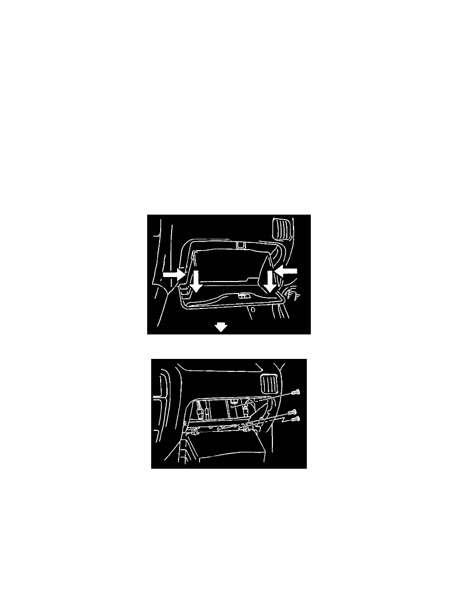
2. Open the glove box.
3. Apply pressure to the sides of the glove box in order to release the two side catches and pull the glove box down.
4. Remove the three bolts and the PCM bracket from behind the glove box.
5. Disconnect the three PCM electrical connectors.
6. Remove the PCM from the passenger compartment.
Installation Procedure
1. Connect the three PCM electrical connectors.
2. Install the PCM bracket to the mounting position behind the glove box.
Notice: Refer to Fastener Notice in Cautions and Notices.