
Metro L4-079 1.3L VIN 2 MFI (2001)
6. The DMM displays the voltage measured at that point.
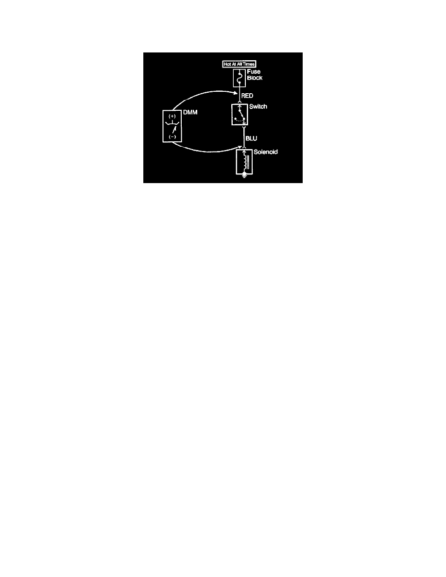
Measuring Voltage Drop
NOTE: Refer to Test Probe Notice in Service Precautions.
The following procedure determines the difference in voltage potential between two points.
1. Set the rotary dial of the DMM to the V (DC) position.
2. Connect the positive lead of the DMM to one point of the circuit to be tested.
3. Connect the negative lead of the DMM to the other point of the circuit.
4. Operate the circuit.
5. The DMM displays the difference in voltage between the two points.
Probing Electrical Connectors
IMPORTANT: Always be sure to reinstall the Connector Position Assurance (CPA) and Terminal Position Assurance (TPA) when reconnecting
connectors or replacing terminals.
Front probe
Disconnect the connector and probe the terminals from the mating side (front) of the connector.
NOTE: Do not insert test equipment probes into any connector or fuse block terminal. The diameter of the test probes will deform most terminals. A
deformed terminal can cause a poor connection, which can result in system failures. Always use the J 3561 6-A Connector Test Adapter kit or the J
42675 Flat Wire Probe Adapter kit in order to front probe terminals. Do not use paper clips or other substitutes as they can damage terminals and
cause incorrect measurements.
Backprobe
Do not disconnect the connector and probe the terminals from the harness side (back) of the connector.
IMPORTANT:
^
Backprobe connector terminals only when specifically required in diagnostic procedures.
^
Do not backprobe a sealed (Weather pack(R) connector, less than a 280 series Metri-Pack connector, a Micro-Pack connector, or a flat wire
(dock and lock) connector.
^
Backprobing can be a source of damage to connector terminals. Use care in order to avoid deforming the terminal, either by forcing the test
probe too far into the cavity or by using too large of a test probe.
^
After backprobing any connector, inspect for terminal damage If terminal damage is suspected, test for proper terminal contact.
Salt Water Spray
Some compounds possess the ability to conduct electricity when dissolved in water such as ordinary salt. By mixing table salt with water in sufficient
quantities, you can enhance the conductive properties of water so that any circuit which may be sensitive to moisture will more readily fail when liberally
sprayed with this mixture.
Mixing 12 ounces of water with approximately 1 tablespoon of salt will yield a salt solution of 5%. Fill a normal spray bottle with this mixture. This
mixture is sufficient to enhance the water's own conductivity. This may cause the circuit to fail more easily when sprayed. Once the mixture is completed,
spray the suspect area liberally with the solution. Then, while monitoring either a scan tool or DMM, manipulate the harness as discussed previously.
Scan Tool Snapshot Procedure
Snapshot is a recording of what a control module on the vehicle was receiving for information while the snapshot is being made. A snapshot may be used
to analyze the data during the time a vehicle condition is current. This allows you to concentrate on making the condition occur, rather than trying to
view all the data in anticipation of the fault. The snapshot contains information around a trigger point that you have determined. Only a single data list