
Monte Carlo V6-204 3.4L DOHC VIN X SFI (1996)
NOTE: GM does not provide a timing mark diagram for belt installation without using the special tool(s) listed below.
TOOLS REQUIRED:
^
J 38613 Cam Hold Down Tool
^
J 38614 Cam Sprocket Holding Tool
NOTICE: If only one (1) bank is to be timed, make sure bank to bank cam timing relationship is one (1) revolution a part. Timing flats should be 180
degrees opposite (right bank versus left bank) when finally timed.
1. Remove all spark plugs.
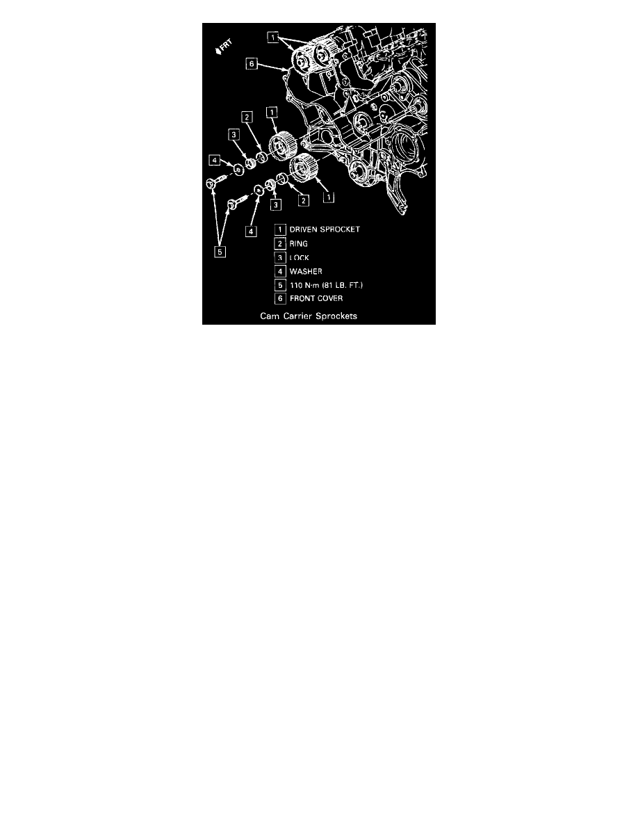
2. Remove all camshaft sprockets.
IMPORTANT: Remove oil from cam hold down tool bolt hole in carrier before installing and tightening bolt.
3. Rotate camshaft flats "up" and install J 38613. Tighten cam hold down tool bolt to 30 Nm (22 lb. ft.).
4. Install all camshaft sprockets.
5. Timing belt by routing it around the idlers and sprockets. DO NOT bend, kink, or pry on belt as damage may occur.
A. Start at intermediate cam sprocket and work counterclockwise.
B. Make sure the belt is installed in direction of rotation.
C. Engage teeth into all sprockets, place rubber hose behind belt at intermediate sprocket and accumulate slack at tensioner location.
6. Tensioner pulley to mounting base.
^
Use flat magnet, tape or cup plug to hold pivot tube in pulley during this step. Otherwise, pivot tube may fall out.
^
After starting pivot bolt, rotate arm counterclockwise to position square lug at 6 o'clock.
TIGHTEN
^
Tensioner pulley bolt to 15 Nm (11 lb. ft.) + 400, using J 36660, or
^
Tensioner pulley bolt to 50 Nm (37 lb. ft.).
IMPORTANT: The arm bushing and pivot must be clean and NOT LUBRICATED.
7. Actuator and side plate.
INSPECT
^
The installed actuator assembly to assure it is free and rotates under its own weight.
8. Pull paper clip (retaining pin), using needle pliers, and discard allowing the pulley to move into the belt.
9. Gently rotate the tensioner pulley 10-15 Nm (89 lb. in. - 11 lb. ft.) counterclockwise in to the belt using the square lug in the arm and engage the
actuator shaft in the arm socket.
10. Rotate engine clockwise (direction of engine rotation as viewed from the front) 3 times minimum to seat the belt. Align the crankshaft reference