
Monte Carlo V6-3.8L SC VIN 1 (2004)
Manifold Pressure/Vacuum Sensor: Testing and Inspection
MANIFOLD ABSOLUTE PRESSURE (MAP) SENSOR DIAGNOSIS
CIRCUIT DESCRIPTION
VIN 1
The MAP sensor responds to changes in intake manifold pressure which gives an indication of the engine load. The MAP sensor has a 5-volt
reference circuit, a low reference circuit, and a signal circuit. The PCM supplies 5 volts to the MAP sensor on the 5-volt reference circuit and
provides a ground on the low reference circuit. The MAP sensor provides a signal to the PCM on the MAP sensor signal circuit, which is relative to
the pressure changes in the manifold. With low MAP, such as during idle or deceleration, the PCM should detect a low MAP sensor signal voltage.
With high MAP such as WOT, the PCM should detect a high MAP sensor signal voltage. This MAP sensor will indicate pressure between 8-208 kPa.
The MAP sensor is also used in order to calculate the BARO when the ignition switch is turned ON, with the engine OFF. The PCM monitors the
MAP sensor signal for voltage outside of the normal range. If the PCM detects a MAP sensor signal voltage that is excessively low, DTC P0107 sets.
If the PCM detects a MAP sensor signal voltage that is excessively high, DTC P0108 sets.
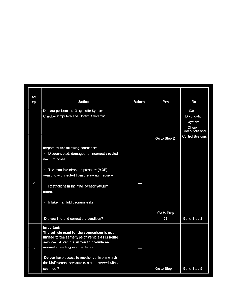
TEST DESCRIPTION
Steps 1-3