
Monte Carlo V6-3.8L VIN K (1998)
Voltage Signal: Description and Operation
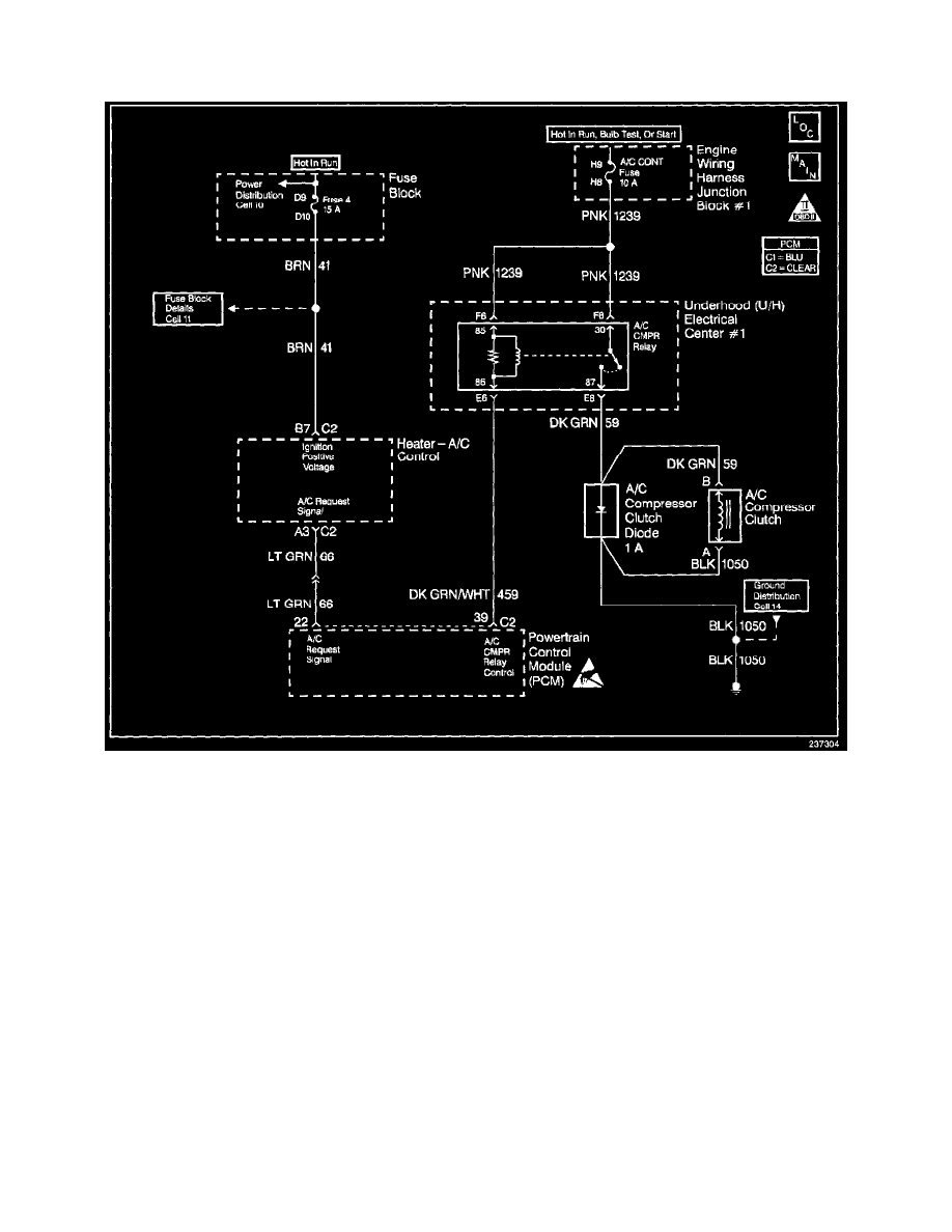
PCM Controlled Air Conditioning
Wiring Diagram
OPERATION
The air conditioning system uses a compressor with variable displacement. This compressor is referred to as the V-5 type compressor. The V-5
compressor meets A/C requirements without cycling. The A/C compressor operation is controlled by the Powertrain Control Module (PCM) for the
following reasons:
^
Improved idle quality during compressor clutch engagement.
^
Improved wide open throttle performance (WOT).
^
Protects the A/C compressor from operation with incorrect refrigerant pressures.
The A/C clutch electrical system consists of the following components:
^
The A/C control head and/or the A/C programmer.
^
The A/C refrigerant pressure sensor.
^
The A/C compressor clutch.
^
The A/C compressor clutch relay.
^
The PCM.
When an A/C mode is selected at the A/C control head, the A/C programmer provides a 12 volt signal to the A/C request circuit. The PCM monitors
the A/C request circuit and controls the A/C compressor relay based on the A/C request signal. This allows the PCM to increase the engine idle speed
just prior to A/C clutch engagement for better idle quality. In addition, the PCM will command the cooling fans ON during A/C operation. The PCM
also monitors the A/C refrigerant pressure sensor circuit. If the A/C refrigerant pressure is too high or low, the PCM will disable the A/C compressor
relay.
The PCM will enable the A/C compressor clutch whenever the engine is running and the A/C has been requested unless one or more of the following