
Monte Carlo V6-3.8L VIN K (1998)
Control Arm: Service and Repair
Front Suspension
Removal Procedure
Tools Required:
J 35917 Tie Rod Puller Ball Joint Remover
1. Raise and suitably support the vehicle.
2. Remove the tire and wheel assembly.
3. Remove the engine splash-shields.
4. Remove the stabilizer to lower control arm insulator clamp bolts.
5. Remove the lower ball joint cotter pin and nut.
6. Use the J 35917 to separate the ball joint from the lower control arm.
7. Remove the lower control arm-to-frame attaching nuts and bolts.
8. Remove the lower control arm.
Installation Procedure
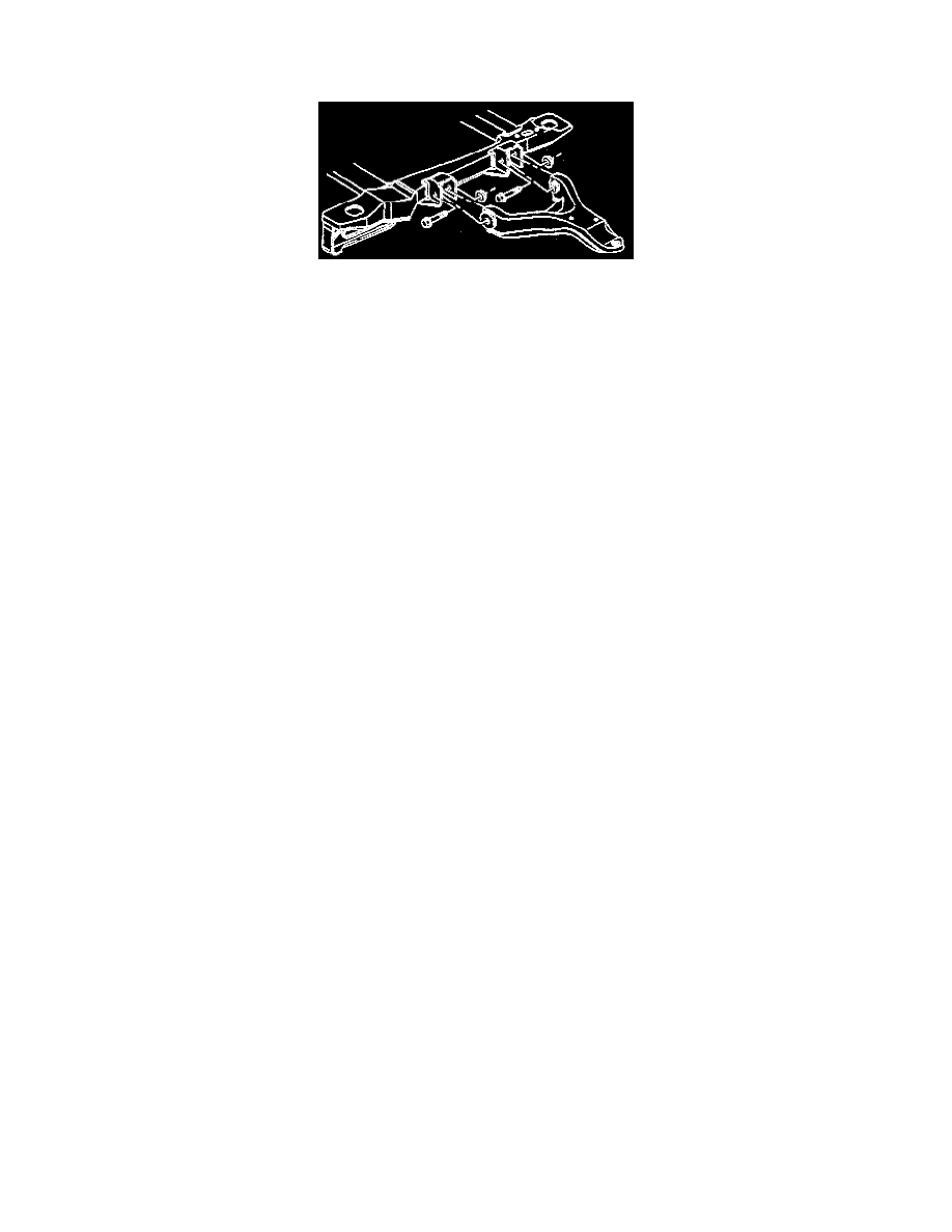
1. Install the lower control arm.
2. Install the lower control arm bolts as shown.
3. Pivot the lower control arm up to the ball joint.
Important: DO NOT tighten more than 60 degrees (1 flat) to align with the hole. DO NOT loosen the nut at any time during the installation.
4. Install the ball joint to the lower control arm nut.
-
Tighten the nut in order to align the next slot in the nut with the cotter pin hole in the stud.
Tighten
-
Tighten the lower control arm-to-frame nuts to 70 N.m (52 ft. lbs.).
-
Tighten the lower ball joint nut to 85 N.m (63 ft. lbs.).
5. Install a new cotter pin.
6. Install the stabilizer shaft to the lower control arm insulator clamp.
Tighten
-
Tighten the stabilizer shaft bushing clamp bolts/screws to 48 N.m (35 ft. lbs.).
7. Install the engine splash shields.
8. Install the tire and wheel assembly.
9. Lower the vehicle.