
Nova/Chevy II L4-1600cc 4ALC Nummi (1988)
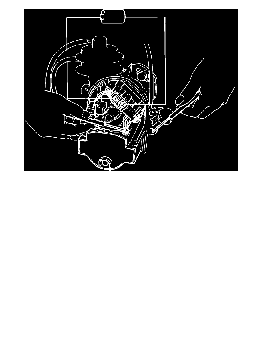
Fig. 5 Inspecting module
1.
Remove distributor cap, then turn ignition switch to ``On'' position.
2.
Check for line voltage at power source as follows:
a. Connect the positive probe from a suitable voltmeter to the positive terminal of the ignition coil.
b. Connect the negative probe of voltmeter to a suitable ground.
c. Voltage reading should be approximately 12 volts.
3.
Inspect power transistor as follows:
a. Connect positive probe of a suitable ohmmeter to the ignition coil negative terminal, then the negative probe to ground, Fig. 4. Voltage
reading should be approximately 12 volts.
b. Connect the positive pole of a 1.5 volt dry cell battery to the pink wire terminal, then the negative pole to the white wire terminal, Fig. 5. Do
not apply voltage for more than 5 seconds or damage to power transistor will occur.
c. Connect the positive probe of a suitable voltmeter to the ignition coil negative terminal, then the negative probe to ground. Voltage reading
should be approximately 0-3 volts. If not, replace module.