
Prizm L4-108 1.8L DOHC VIN 8 MFI (1998)
Flex Plate: Service and Repair
REMOVAL PROCEDURE
^
Tools Required
-
J 8001 Dial Indicator Set
-
J 26900-13 Magnetic Base
-
J 36660 Torque Angle Meter
CAUTION: Refer to Battery Disconnect Caution in Service Precautions.
1. Disconnect the negative battery cable.
2. Remove the transmission assembly.
3. If equipped with a manual transmission, remove the clutch and pressure plate.
4. Inspect the ring gear. Replace the flywheel (2) if the ring gear is damaged, cracked or worn.
5. Inspect the surface which is contacting the clutch disc on manual transmission
equipped vehicles. Replace the flywheel if the surface is damaged or excessively worn.
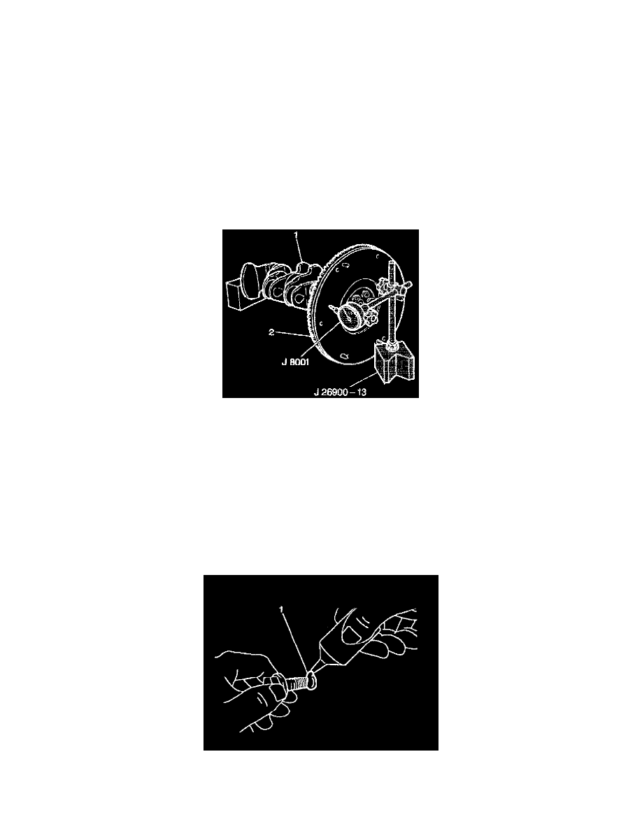
6. Use a J3001 with a J26900-13 in order to measure the flywheel (2)
for face runout. Replace the flywheel if the runout exceeds 0.1 mm (0.004 inch).
7. Mark the flywheel-to-engine position.
8. Remove the eight flywheel retaining bolts.
9. Remove the flywheel from the crankshaft.
10. Clean the grease and dirt from the flywheel (2) outer surfaces using a suitable solvent.
INSTALLATION PROCEDURE
1. Install the flywheel to the crankshaft. Align the flywheel-to-engine marks.
NOTICE: Do not apply an excessive amount of sealant to the flywheel retaining bolt threads. Applying too much sealant will result in the sealant
overflowing the bolt seat. This could cause the bolt to break loose during vehicle operation.
2. Apply GM P/N 12345493, or the equivalent, to the flywheel retaining bolt threads (1).