
R 10 P/U 2WD L6-292 4.8L (1988)
Installing The Clutch Plate & Hub Assembly
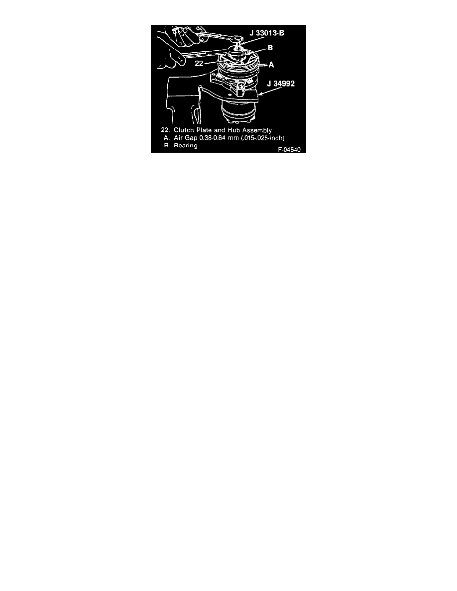
2. Clutch plate and hub assembly (2).
^
Make sure the contact surfaces of the clutch plate (22) and the pulley (26) are clean.
^
Remove the forcing screw tip from J 33013-B and reverse the body direction on the center screw.
^
Install J 33013-B with bearing (B).
^
Back off J 33013-B body enough to allow the center screw to be threaded against the end of the compressor shaft (38).
^
Hold the center screw with a wrench and tighten the hex portion of J 33013-B body while pressing the hub onto the shaft (38). After tightening
the body several turns, remove J 33013-B and check that the shaft key (21) is properly in place in the keyway, then install the clutch plate and
hub assembly (22) to its final position.
^
Measure the air gap between contact surfaces of the clutch plate and hub assembly (22) and the pulley (26). The gap should be 0.38-0.64 mm
(0.015-0.025-inch).
^
Remove J 33013-B
Inspect
^
Position of the shaft (38) (even with or slightly above the clutch hub).
^
Use J 33027 to hold the clutch plate and hub assembly (22).
Tighten
^
Shaft nut (21) to 17 N.m (12 ft. lbs.) with J 33022.
-
Hand spin the pulley (26) to check for free rotation.
-
Remove the compressor from J 34992.
Pulley and Bearing Assembly