
R 30 P/U 2WD L6-292 4.8L (1988)
body several turns, remove J 33013-B and check that the shaft key (21) is properly in place in the keyway, then install the clutch plate and hub
assembly (2) to its final position.
^
Measure the air gap between contact surfaces of the clutch plate and hub assembly (2) and the pulley (5). The gap should be 0.38-0.64 mm
(0.015-0.025-inch).
^
Remove J 33013-B.
Inspect
^
Position of the shaft (20) (even with or slightly above the clutch hub).
^
Use J 33027 to hold the clutch plate and hub assembly (2).
Tighten
^
Shaft nut (1) to 16 N.m (12 ft. lbs.) with J 33022.
-
Hand spin the pulley (5) to check for free rotation.
^
Remove J 33026.
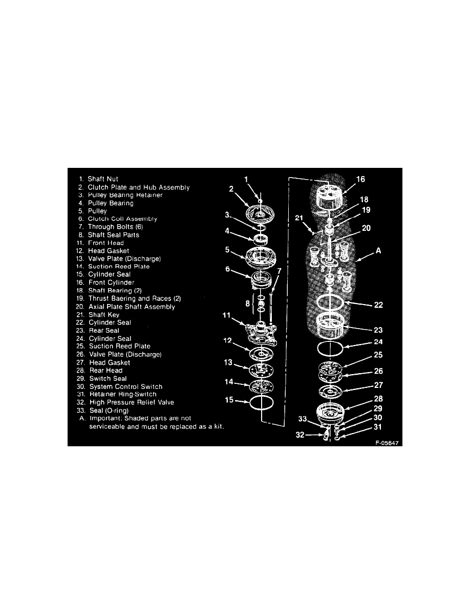
Pulley and Bearing Assembly
HR-6 Component View
Remove or Disconnect
Tools Required:
J 6983 Snap Ring Pliers
J 8092 Driver Handle
J 9398-A Pulley Bearing Remover
J 33020 Pulley Puller
J 33023-A Puller Pilot
1. Clutch plate and hub assembly (2).