
S10/T10 Blazer 2WD V6-262 4.3L VIN Z (1994)
variety of tips to permit touching them to connectors, bare wires, insulated wires, or even wires within wiring harnesses. To check the tester before use,
briefly touch the clip to one side of the battery and the probe to the other. 12-volt testers are NOT sensitive to polarity in a circuit and can be connected
either way.
The 12-volt test lamp generally has a sharp probe tip so it can be inserted into connector terminals or through the wire insulation for testing. It is
important to keep the probe tip sharp to minimize damage to wire insulation. When the test is complete at a particular point, be sure to tape any holes
made in wire insulation.
The unpowered test lamp is used on an open circuit. One lead of the test lamp is grounded and the other lead is moved around the circuit to find the
open. Depending on the physical layout of the circuit, sometimes it is easier to start at the voltage supply, and other times it is easier to start at the circuit
load or ground circuit.
Once one becomes familiar with the test lamp and the brilliance of the bulb in a normal circuit, high-resistance circuits can be recognized by the effect
they have on the bulb. As the current drops in a high-resistance circuit, the bulb in the test lamp glows less brightly. Although the 12-volt test lamp
cannot be used as a foolproof test for high resistance, a less than normal brilliance of the lamp is an indication of circuit high resistance. Further testing
will verify the condition and locate the cause.
NOTE: Test lamps are to be used only on circuits that do not contain solid-state devices. If a test lamp is used in a circuit containing a solid-state
device, the current that the test lamp would draw would be above the current that the solid-state device would be able to handle. Using a test lamp on a
solid-state device may damage the device.
Self-Powered Test Lamp
This lamp is a pencil-shaped unit with a self-contained battery, a 1.5-volt lamp bulb, a sharp probe, and a ground lead fitted with an alligator clip.
This test is used mainly for testing components that are disconnected from the vehicle voltage supply. The powered test lamp is also useful for testing
suspected high resistance points in a circuit such as connectors and ground circuits that are corroded or loose.
General
The following three types of meters are generally used for diagnosis: ammeter, ohmmeter, and voltmeter.
These meters are available in two designs: analog (needle-type) and digital (electronic display-type).
NOTE: The correct type of meter must be used when diagnosing circuits containing solid-state devices. Incorrect use of the meters will result in damage
to the solid-state device.
Analog meters may be used for any circuit not containing a solid-state device, while a digital meter MUST be used to diagnose any circuit with a
solid-state device. Circuits which contain a solid-state device, such as the engine control module, should be tested only with a 10-megohm or higher
impedance digital multimeter (J 39200 or equivalent).
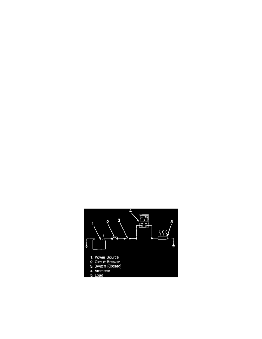
Ammeter
Ammeter