
S10/T10 Blazer 2WD V6-262 4.3L VIN Z (1994)
branches, or connectors. This will help prevent moisture from bridging adjacent splices and causing damage.
3. Strip the Insulation
If it is necessary to add length of wire to the existing harness, be certain to use the same size as the original wire.
To find the correct wire size either find the wire on the schematic page and convert the metric size to the equivalent AWG size or use an AWG
wire gage. If unsure about the wire size, begin with the largest opening in your wire stripper and work down until you get a clean strip of the
insulation. Strip approximately 7.5 mm (5/16 in) of insulation from each wire to be splices. Be careful to avoid nicking or cutting any of the wires.
Check the stripped wire for nicks or cut strands. If the wire is damaged, repeat this procedure after removing the damaged section.
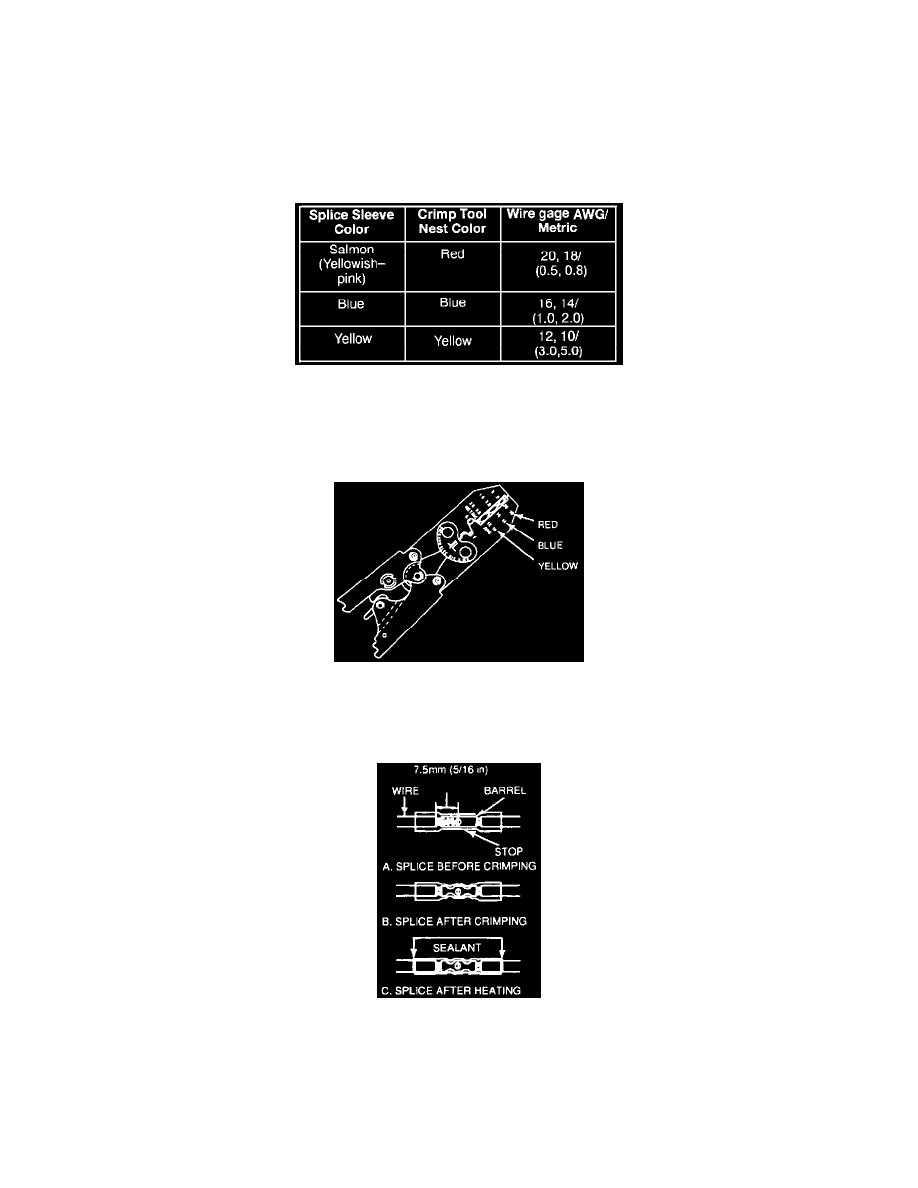
Crimp And Seal Splice Sleeve Chart
4. Select and Position the Splice Sleeve
Select the proper splice sleeve according to wire size. The splice sleeves and tool nests are color coded. Refer above to determine the correct
splice sleeve.
Hand Crimp Tool
Using the J 38125-8 splice crimp tool, position the splice sleeve in the proper color nest of the hand crimp tool. Place the splice sleeve in the nest
so that the crimp falls midway between the end of the barrel and the stop.
Seal Splice Sequence
The splice sleeve has a stop in the middle of the barrel to prevent the wire from going further. Close the handles slightly to hold the splice sleeve
firmly in the proper nest.