
S10/T10 Blazer 2WD V6-262 4.3L VIN Z (1994)
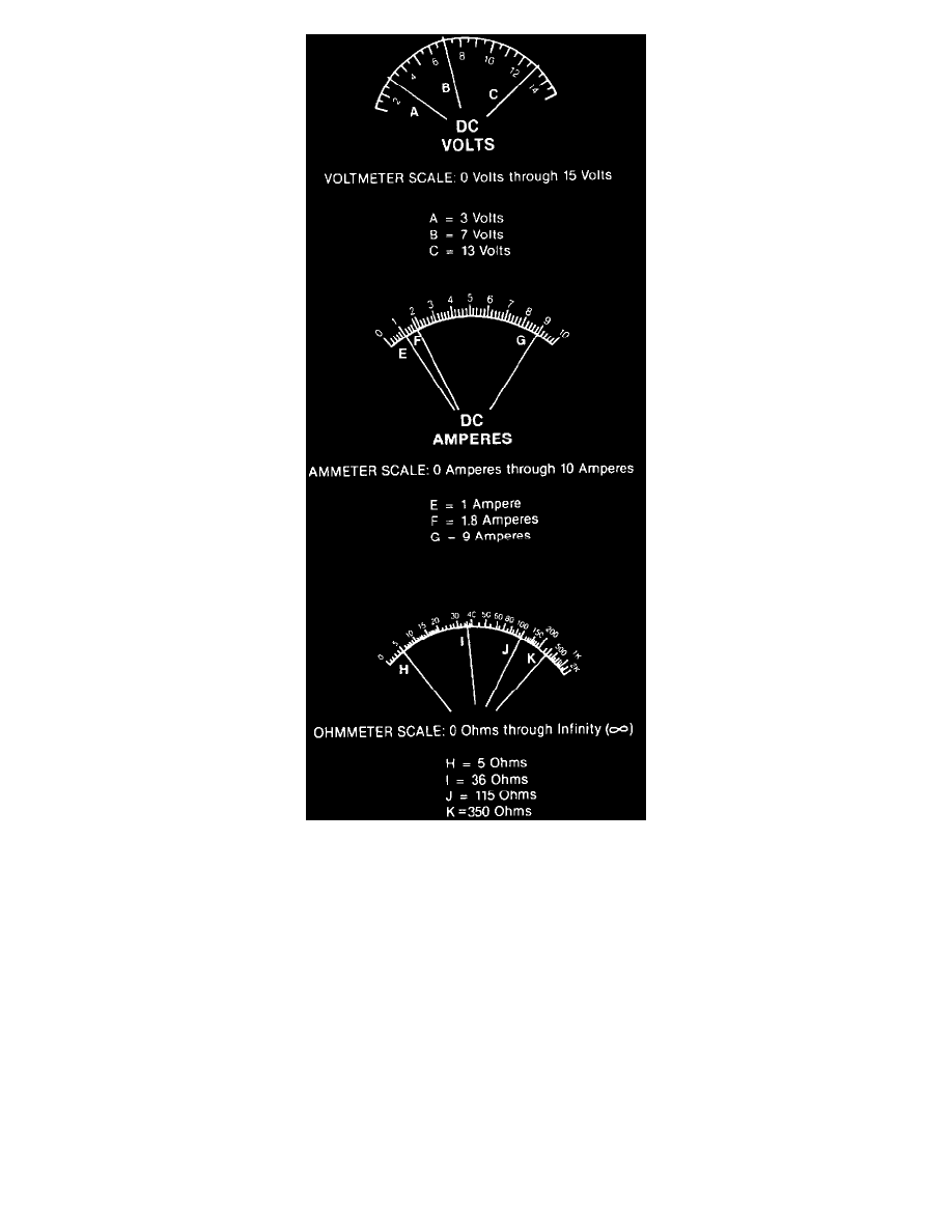
Meter Scales
The voltmeter (properly observed) will give the technician more information than the ammeter, ohmmeter, and test lamp combined. Its application for
diagnosis here is to measure the electrical pressure (voltage) drop in a resistance circuit. Voltage drop is a reduction or "using up" of the voltage to push
electricity through a resistance. It can be compared to the pressure of water flowing through a metering valve.
Low voltage to a lamp makes the lamp glow dimly. This can be caused by low source voltage (battery discharge or low alternator output) or by high
resistance in the circuit due to a poor connection. Before making any meter measurements, it is important to review the relationship between current,
voltage and resistance.
Determining voltage drop is important because it provides the following information:
^
Too high of a voltage drop indicates excessive resistance. If, for instance, a blower motor runs too slowly or a lamp glows too dimly, one can be
sure there is excessive resistance in the circuit. By taking voltage drop readings in various parts of the circuit, the problem (corroded terminals, for
example) can be isolated.
^
Too low of a voltage drop indicates low resistance. If, for instance, a blower motor runs too fast, the problem could be isolated to a low resistance
in a resistor pack by taking voltage drop readings.
^
Maximum allowable voltage drop under a load is critical, especially if there is more than one high resistance problem in a circuit. It is important
because, like all resistances, all voltage drops are cumulative. Corroded terminals, loose connections, and similar problems reduce the voltage
available across the key circuit components. The current flow is reduced in the circuit, and all of the affected components operate at less than peak
efficiency. A small drop across wires (conductors), switches, connectors, etc., is normal. This is due to the resistance of the conductors but should