
S10/T10 Blazer 2WD V6-4.3L VIN X (2003)
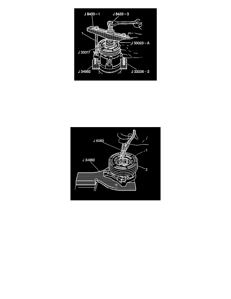
8. With the compressor mounted on the J 34992, position the pulley rotor (1) and the bearing assembly on the front head.
9. Position the J 33017 and the J 33023-A directly over the inner race of the bearing.
10. Position the J 8433-1 on the J 33023-A.
11. Assemble the 2 through bolts and the washers through the puller bar slots.
12. Thread the through bolts into the J 34992. Ensure that the thread of the through bolts engage the full thickness of the J 34992.
13. Tighten the center screw in the J 8433-1 in order to force the pulley rotor and bearing assembly onto the compressor front head. If the J 33017
slips off direct in-line contact with the inner race of the bearing, perform the following steps:
13.1. Loosen the J 8433-3.
13.2. Realign the installer and the pilot in order to ensure that the J 33017 properly clears the front head.
14. Use the J 6083 in order to install the following components:
-
The pulley rotor (1)
-
The retaining ring (2)
15. Install the clutch plate and hub assembly.
V7 - Direct Mount
CLUTCH ROTOR AND/OR BEARING INSTALL (V7 - DIRECT MOUNT)
TOOLS REQUIRED
-
J 33013-B Hub and Drive Plate Remover/Installer
-
J 33017 Pulley and Bearing Installer
-
J 41790 Compressor Holding Fixture