
S10/T10 Blazer 4WD V6-262 4.3L VIN Z (1994)
Wiring Schematic For Enabling The Status Lamps
OPERATION
When pin J of the Data Link Connector (DLC) is connected either to pin A of the DLC or to a good ground while the ignition is on, the
diagnostics routine of the Transfer Case Control Module (TCCM) is activated. When the diagnostics routine is activated, the transfer case selector
switch 4HI and 4LO status lamps flash the diagnostic codes.
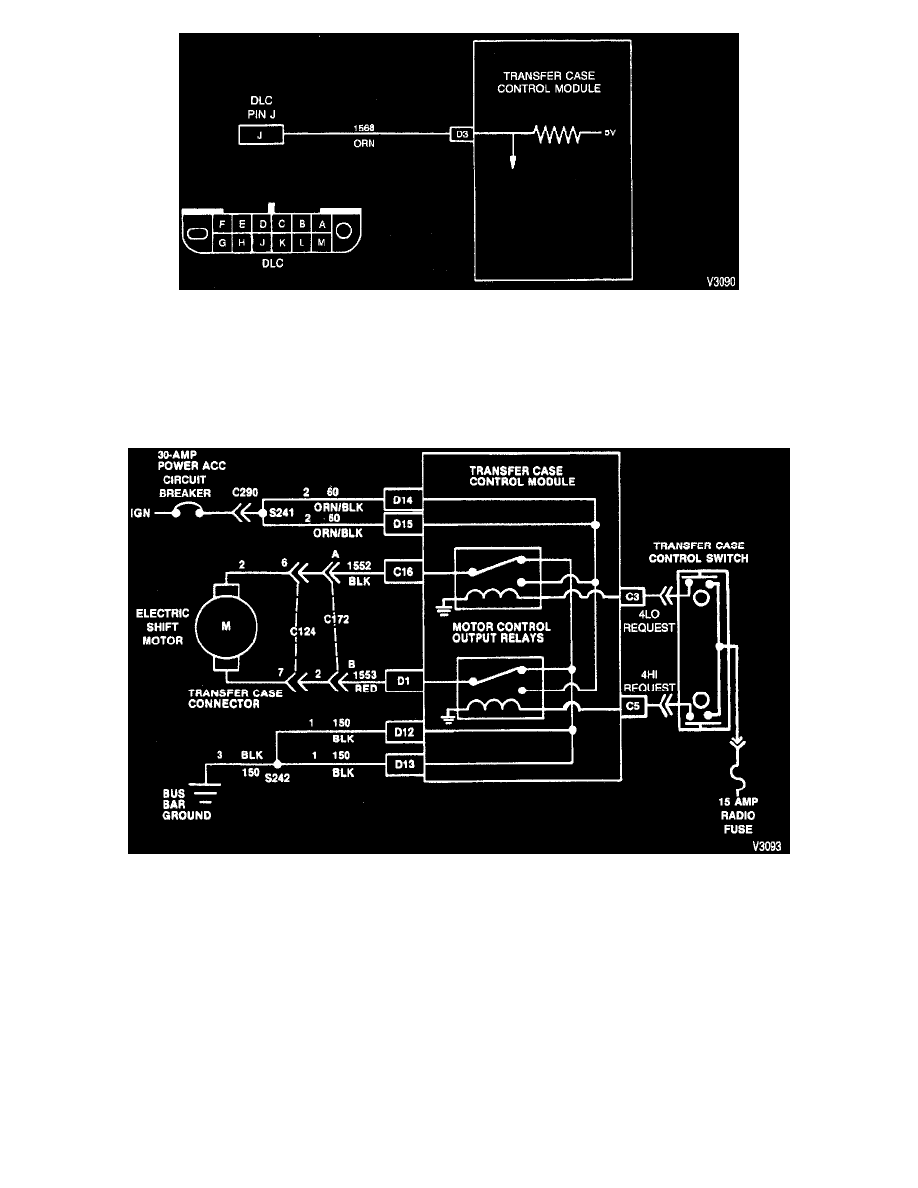
Electric Shift Motor Outputs
Electric Shift Motor Schematic
OPERATION
The Transfer Case Control Module (TCCM) provides the output for the electric shift motor as the schematic shows.
-
Motor control is achieved by energizing one of the two motor control relays located in the TCCM, by way of the transfer case selector switch.
The TCCM operates the motor in one direction by energizing one relay while the second relay is de-energized. The TCCM operates the motor in
the reverse direction by energizing the second relay while the first relay is de-energized.
-
Motor power to actuate the motor drive relays is input at TCCM connector pins D14 and D15. This power is supplied by the ignition through
the 30-amp power circuit breaker.
-
Motor ground is input at TCCM connector pins D12 and D13 to provide the return line for the motor drive relays.
4HI and 4LO Status Lamps Outputs