
S10/T10 P/U 2WD L4-151 2.5L (1988)
Crankshaft Gear/Sprocket: Service and Repair
Some models may experience engine knocking due to loose or improperly seated camshaft gears. This condition is affected by engine speed, rather
than loads imposed on the engine. To diagnose this condition, remove all drive belts and listen to engine with a stethoscope placed against timing gear
cover while accelerating slowly between 700 and 1000 RPM. Timing gear noise is most noticeable at approximately 800 RPM and can be heard at the
oil pan between cylinders 3 and 4 as well as at the timing gear cover. If gears are determined to be at fault, proceed as follows:
1.
Remove valve cover, rocker arms and engine front cover.
2.
Check camshaft end clearance, which should measure .0015-.0050 inch.
3.
Install crankshaft pulley and tighten retaining bolt to specifications.
4.
Position a magnetic dial indicator on front of engine block with probe contacting one tooth of camshaft gear.
5.
Check backlash at four points on camshaft gear by rotating gear back and forth. Backlash should measure .0005-.0095 inch.
6.
If camshaft end clearance exceeds .0050 inch, or backlash exceeds .0095 inch, the timing gears and/or cam gear thrust plate must be replaced.
7.
If gear backlash exceeds .0095 inch, both the camshaft and crankshaft gears must be replaced.
REMOVAL
1.
Disconnect battery ground cable and drain cooling system.
2.
Remove side cover as described under SIDE COVER.
3.
Disconnect power steering reservoir and set aside, then remove upper fan shroud, drive belts, fan and pulley.
4.
Remove crankshaft pulley and hub.
5.
Remove front cover.
6.
Rotate crankshaft until timing marks on crank and camshaft timing gears are aligned.
7.
Remove distributor cap and plug wire assembly, mark position of rotor and distributor body, disconnect electrical connectors and remove
distributor.
8.
Remove oil pump driveshaft cover and driveshaft.
9.
Remove air cleaner and EGR valve.
10.
Disconnect vacuum hoses at intake manifold and thermostat housing, then remove rocker cover.
11.
Remove valve lifters as described under HYDRAULIC ROLLER VALVE LIFTERS
12.
Disconnect hoses and transmission cooler lines from radiator, as equipped, plug cooler lines, then remove radiator.
13.
On models equipped with A/C, proceed as follows:
a.
Remove A/C condenser baffles.
b.
Discharge A/C system.
c.
Disconnect A/C refrigerant hoses from A/C condenser.
d.
Remove condenser mounting bolts, then the condenser.
14.
On all models, remove headlamp bezel, grille and bumper filler panel.
15.
Remove bolts securing camshaft thrust plate, then withdraw camshaft from engine, taking care not to damage cam bearings.
16.
Inspect timing gear on crankshaft and replace as needed.
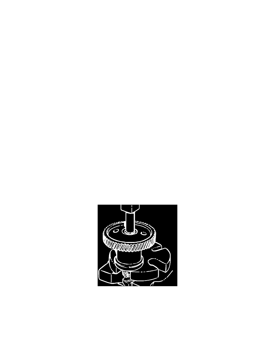
Fig. 7 Camshaft Timing Gear Removal
CAMSHAFT DISASSEMBLY
1.
Position adapter tool No. J-971 or equivalent on a press.
2.
Insert camshaft through adapter with timing gear facing up, Fig. 7.
3.
Secure adapter in press, then press shaft out of gear using spacer. Align thrust plate so that plate is not damaged by Woodruff key as camshaft
is pressed out of gear.
CAMSHAFT ASSEMBLY
1.
Support rear of front camshaft journal in press using adapters.