
S10/T10 P/U 2WD L4-2.2L VIN 4 (1995)
should be used whenever possible (after a catastrophic compressor failure) to protect the expansion device (orifice tube or TXV) from debris. Delphi
V5 and V7 compressors already have this screen installed in the suction port of the compressor and do not need an additional screen installed.
The J 44551 Suction Screen kit contains three different screen sizes. It is important to select the correct size screen that will press fit into the suction
port of the compressor hose assembly. The screen should not be installed loose inside the hose assembly.
1. Insert the J 44551-6 sizing tool into the suction hose to select the correct size suction screen.
2. Insert the suction screen into the compressor end of the suction hose.
3. Select and install the correct mandrel to the J 44551-5.
4. Install the J 44551-5 screen installation tool over the end of the suction hose and the suction screen.
IMPORTANT: Correct placement of the J 44551 is critical.
5. Tighten the forcing screw of the J 44551-5. The suction screen is fully installed when the screen is flush with the end of the suction hose fitting.
6. Remove the J 44551-5 suction screen tool from the suction hose.
7. Install the J 44551-1 Suction Screen Notification Label.
8. Remove the A/C compressor drain plug, if equipped. Drain the PAG oil from the A/C compressor. Rotate the compressor input shaft to assist in
draining the PAG oil from the A/C compressor.
9. Install the A/C compressor drain plug, if equipped.
10. Install the A/C compressor.
11. Remove the blocked orifice tube or TXV adapter (front/rear systems only).
12. Install a new orifice tube or remove the TXV adapter.
-
Inspect the original TXV for debris.
-
Clean or replace the original TXV as needed.
-
For front/rear systems, be sure both expansion devices (orifices or TXVs) are installed.
IMPORTANT:
-
Install the in-line filter on front A/C systems before the orifice tube.
-
Install the in-line filter on front/rear A/C systems before the "Y" in the evaporator tube.
-
Do not allow metal burrs to enter the evaporator tube during cuffing or when removing the burrs. Because of limited space in the engine
compartment, it may be necessary to remove the system's existing orifice tube and install a filter with an orifice.
13. Follow these steps for in-line filter installation:
13.1. Using a tubing cutter, cut the marked section of the evaporator tube.
13.2. Remove the burrs from the evaporator tube.
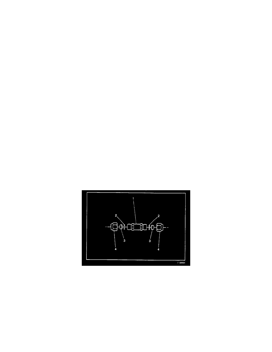
13.3. Remove the nuts (4), the ferrules (3) and the O-rings (2) from the A/C refrigerant filter (1).
IMPORTANT: Do not install the O-rings (2)in this step.
13.4. Push the nuts (4) and the ferrules (3) over each of the evaporator tube halves. Install the ferrules (3) with the small end toward the nut (4).
13.5. Install the A/C refrigerant filter (3) to the evaporator tube (2) with the flow arrow pointing towards the evaporator.
13.6. While holding the evaporator tube in the A/C refrigerant filter (1), tighten the nuts (4) to the A/C refrigerant filter (1).
TIGHTEN
Nuts to 15 Nm (11 lb ft).
13.7. Remove the nuts (4) from the A/C refrigerant filter (1).
13.8. Coat the O-rings (2) with 525 viscosity refrigerant PAG oil
13.9. Install the O-rings (2) to the evaporator tube halves.