
S10/T10 P/U 2WD L4-2.2L VIN 4 (1995)
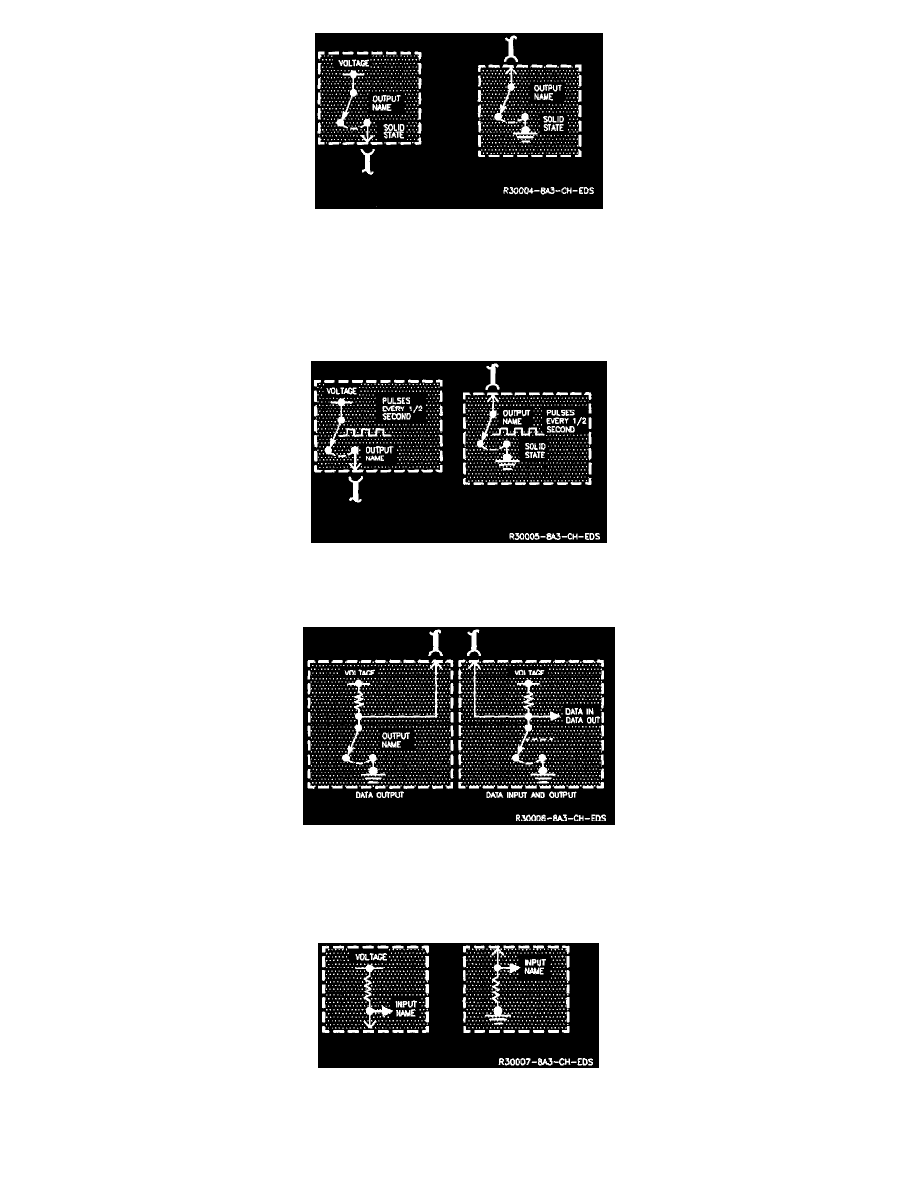
Solid State Switch
Outputs
The Solid State Switch is used to turn a circuit outside the module. When the switch closes, the voltage or ground shown will be applied to the connected
circuit. Additional information about what makes the switch close is often provided. The voltage controlled by the switch may be measured just as if it
were a mechanical switch.
Solid State Switch
These symbols are similar to the solid State Switch. The pulses represent the rate at which the switch is turned on and off.
Special Versions Of The Solid State Switch
These two symbols are special versions of the Solid State Switch. They represent serial data inputs and outputs. Serial data consists of coded groups of
voltage pulses transmitted at high speed. These pulses cannot usually be measured with a Digital Voltmeter. There are cases however where procedures
in System Diagnosis may describe such measurements. A Scan tool can often read and display this data.
Solid State Switch
Inputs