
S10/T10 P/U 2WD L4-2.2L VIN 4 (1995)
Crankshaft Position Sensor: Description and Operation
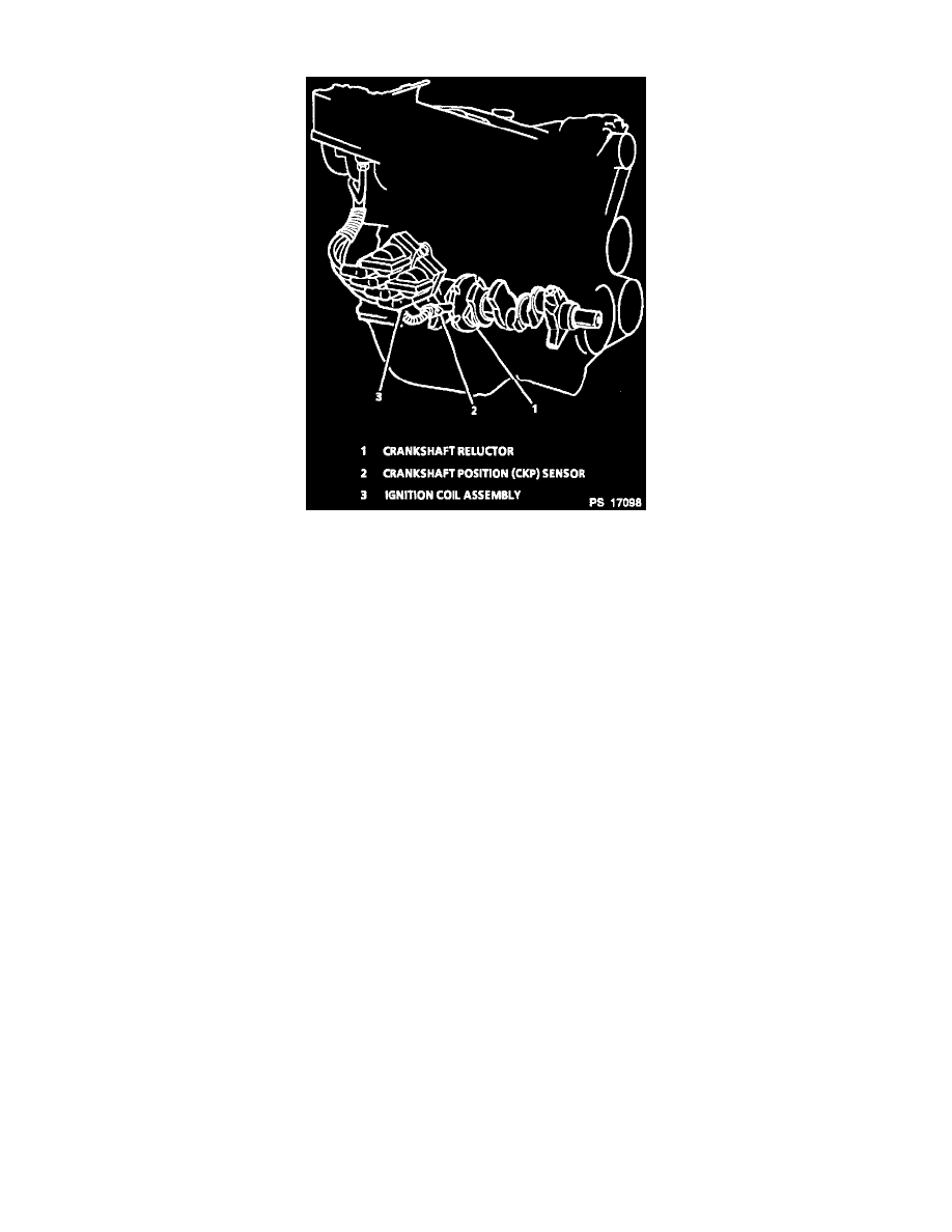
Sensor To Crankshaft Reluctor Relationship
DESCRIPTION
This system uses a magnetic Crankshaft Position (CKP) sensor mounted remotely beside the electronic Ignition Control Module (ICM), which
protrudes into the block to within approximately 0.050" of the crankshaft reluctor. Image illustrates a typical sensor in relationship to the
crankshaft reluctor. The reluctor is a special wheel cast into the crankshaft with seven slots machined into it, six of which are equally spaced (60°
apart). A seventh slot is spaced 10° from one of the other slots and serves to generate a "sync-pulse." As the reluctor rotates as part of the
crankshaft, the slots change the magnetic field of the sensor, creating an induced voltage pulse.
OPERATION
Based on the CKP sensor pulses, the ICM sends reference signals to the Powertrain Control Module (PCM) which are used to indicate crankshaft
position and engine speed. The ICM will continue to send these reference pulses to the PCM at a rate of one per each 180° of crankshaft rotation.
The PCM will activate the fuel injector based on the recognition of every other reference pulse beginning at a crankshaft position of 120° after top
dead center. By comparing the time between pulses, the ICM can recognize the pulse representing the seventh slot (sync pulse) which starts the
calculation of ignition coil sequencing.
The second crank pulse following the "sync pulse" signals the EI module to fire the number 2-3 ignition coil and the fifth crank pulse signals the
module to fire the number 1-4 ignition coil.