
S10/T10 P/U 2WD V6-262 4.3L VIN W CPI (1992)
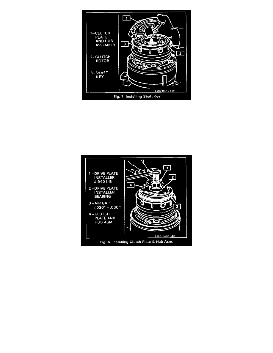
1. Install the shaft key into the hub key groove (Fig. 7). Allow the key to project approximately 4.8mm (3/16") out of the keyway.
The shaft key is curved slightly to provide an interference fit in the shaft key groove of the hub.
2. Be sure the frictional surface of the clutch plate and the clutch rotor are clean before installing the Clutch Plate and Hub assembly.
3. Align the shaft key with the shaft keyway and place the Clutch Plate and Hub assembly Onto the compressor shaft.
NOTICE: To avoid internal damage to the compressor, do not drive or pound on the clutch hub or shaft.
4. Install the Clutch Plate and Hub Installer J 9401-B as illustrated in Figure 8.
5. Hold the hex portion of the Installer Body J 9401-B with a wrench and tighten the center screw to press the hub onto the shaft until there is a
0.5-7.6mm (0.20-0.30") air gap between the frictional surfaces of the clutch plate and clutch rotor.
6. Install a new shaft nut with the small diameter boss of the nut against the crankshaft shoulder, using Thin Wall Socket J 9399-A. Hold the Clutch
Plate and Hub assembly with Clutch Hub Holding Tool J 33027-A, and tighten to 14 N.m (10 lb.ft.) torque, using a 0-60 N.m (0-25 lb.ft.) torque
wrench.
7. If operation is performed with compressor on vehicle, connect drive belt, tighten mounting brackets and adjust belt tension.
4 Pole Clutch
V-GROOVE TYPE - 4 POLE CLUTCH
Remove or Disconnect
1. Remove the Clutch Plate and Hub assembly.