
S10/T10 P/U 2WD V6-262 4.3L VIN W CPI (1992)
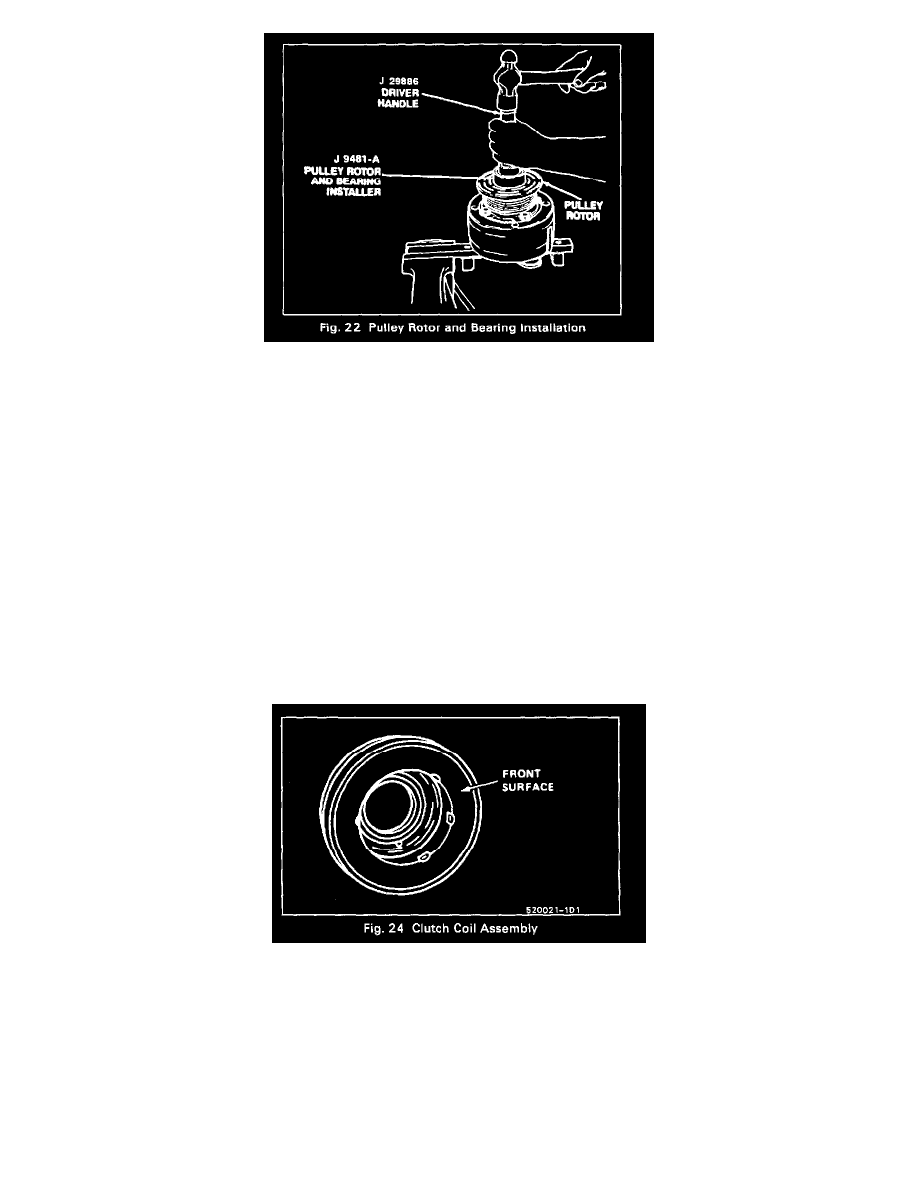
5. With the compressor mounted to the J 25008-A Holding Fixture, position the Rotor and Bearing Assembly on the front head (Fig. 22). Using
Rotor and Bearing Installer J 9481-A and Universal Handle J 29886 drive the rotor and bearing assembly onto the front head. With the Installer
assembled to the Handle as shown in Figure 22, force will be applied to the inner race of the bearing when installing the assembly onto the front
head of the compressor.
6. Install rotor and bearing assembly retainer ring, using Snap Ring Pliers J 6083 (Fig. 9).
7. Reinstall clutch plate and hub assembly as described previously.
Clutch Coil and/or Pulley Rim
V-Groove Drive - 4 Pole Clutch
Remove or Disconnect
Perform Steps 1 through 4 of COMPRESSOR CLUTCH ROTOR AND/OR BEARING removal procedure but do not loosen or remove the pulley rim
mounting screws until the Clutch Rotor, Coil and Pulley Rim assembly have been removed from the Front Head. Be careful not to drop the Puller Guide
J 25031 when removing the assembly.
2. Remove the pulley rim mounting screws and discard.
3. Slide the pulley rim off the Rotor and Hub assembly The Pulley Rim and the Clutch Coil (Fig. 24) are replaceable at this point.
Install or Connect