
S10/T10 P/U 2WD V6-262 4.3L VIN W CPI (1992)
Removing The Lower Ball Joint
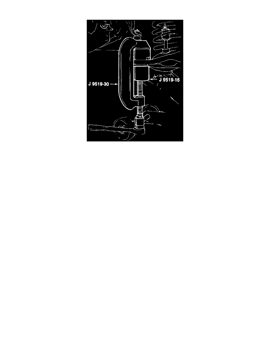
Installing The Lower Ball Joint
SPECIAL TOOLS REQUIRED (or equivalents)
^
J-9519-D, Ball joint remover and installer set.
^
J-23742, Ball joint separator.
REMOVE OR DISCONNECT
1. Raise the vehicle and support the frame with suitable safety stands.
2. Wheel and tire assembly. Place a floor jack under the control arm spring seat and raise it until it supports the control arm.
WARNING: Floor jack must remain under the control arm spring seat during removal and installation to retain the spring and control
arm in position. Failure to do so could result in personal injury.
3. Caliper and support with a piece of wire to prevent damage to the brake line.
4. Cotter pin (68) and the nut (67). Use J-23742 to break the ball joint loose from the knuckle.
5. Lower control arm (40) out of the opening in the splash shield. Use a putty knife or similar tool to guide control arm past splash shield.
NOTE: Block the knuckle assembly out of the way by placing a wooden block between the frame and upper control arm.
6. Grease fittings and lower ball joint (69) from the lower control arm (40).
7. Inspect the tapered hole in the steering knuckle and remove any dirt. If the hole is out of round, deformed or damaged, the knuckle must be
replaced.
INSTALL OR CONNECT
1. Press the new ball (69) joint into the lower control arm (40) using J-9519-D and locate the grease seal facing inboard.
2. Ball joint stud into the steering knuckle.
CAUTION: When fasteners are removed, always reinstall them at the same location from which they were removed and use the correct torque
value. If a fastener needs to be replaced, use a fastener of the correct size and strength. Failure to do so may result in component/system damage or
malfunction.
3. Stud nut (67) onto the stud and tighten to 113 Nm (83 ft lbs). Align the slot in the stud nut with the hole in the stud by tightening.
4. New cotter pin (68) to the stud.
5. Grease fittings and lubricate the ball joint until grease appears at the seal.
6. Caliper.
7. Wheel and tire assembly, then lower the vehicle.
8. Check the front end alignment.