
S10/T10 P/U 4WD V6-4.3L VIN X (1996)
15.
Hand start the new transfer case selector switch and tighten to 24 Nm (18 lb ft).
16.
Ensure that the alignment feature of the vacuum harness connector is oriented correctly to engage the alignment post/pin of the transfer case
selector switch and connect the harness to the switch.
17.
Lower the vehicle and connect the negative battery cable.
18.
Install the GM Campaign Identification Label.
1994 T-Pickup
1.
Disconnect the negative battery cable.
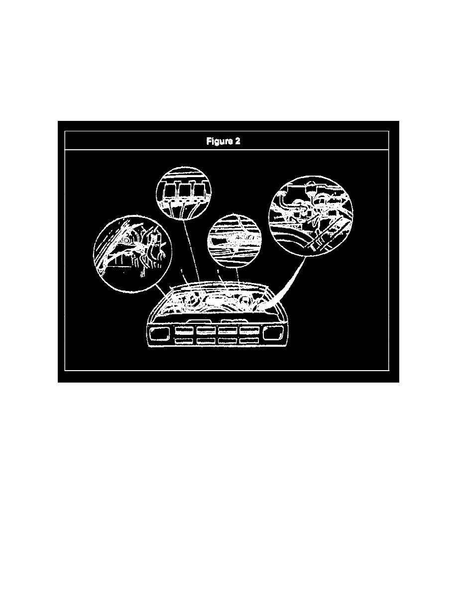
2.
Locate the new vacuum switch, bracket, and hose assembly so that the hole in the bracket align with the front inboard nut that is molded into the
top of the coolant reservoir as shown in Figure 2.
3.
Using the bolt provided in the kit, switch the vacuum switch, bracket, and hose assembly to the coolant reservoir by hand at starting the bolt.
4.
With the vacuum switch, bracket and hose assembly positioned as shown in Figure 2, tighten the bolt to 10 Nm (88 lb in).
5.
Locate the vacuum hose leading from the front axle vacuum actuator, located under the battery tray, to the vacuum switch mounted on the transfer
case. This hose is routed up from the axle vacuum actuator and then rearward towards the cowl area inside the right fender as shown in Figure 2.
6.
Select a point on the vacuum hose, which was located in the previous step, that will be lower in the vehicle than the new vacuum switch and will
not result in the loading or stretching of either the existing or new hoses when they are connected together.
Important
The location where the vacuum line is tapped into must be lower than the vacuum switch to ensure condensation cannot accumulate in the switch,
possibly resulting in a switch malfunction.
7.
Cut the existing vacuum hose at the point located in the previous step, and connect the ends of the cut vacuum hose to the tee fitting that is a part
of the new vacuum switch and hose assembly.
8.
Connect the new wiring harness to the vacuum switch and ensure the locking feature of the connector is engaged.