
S10/T10 P/U 4WD V6-4.3L VIN X (1996)
4.
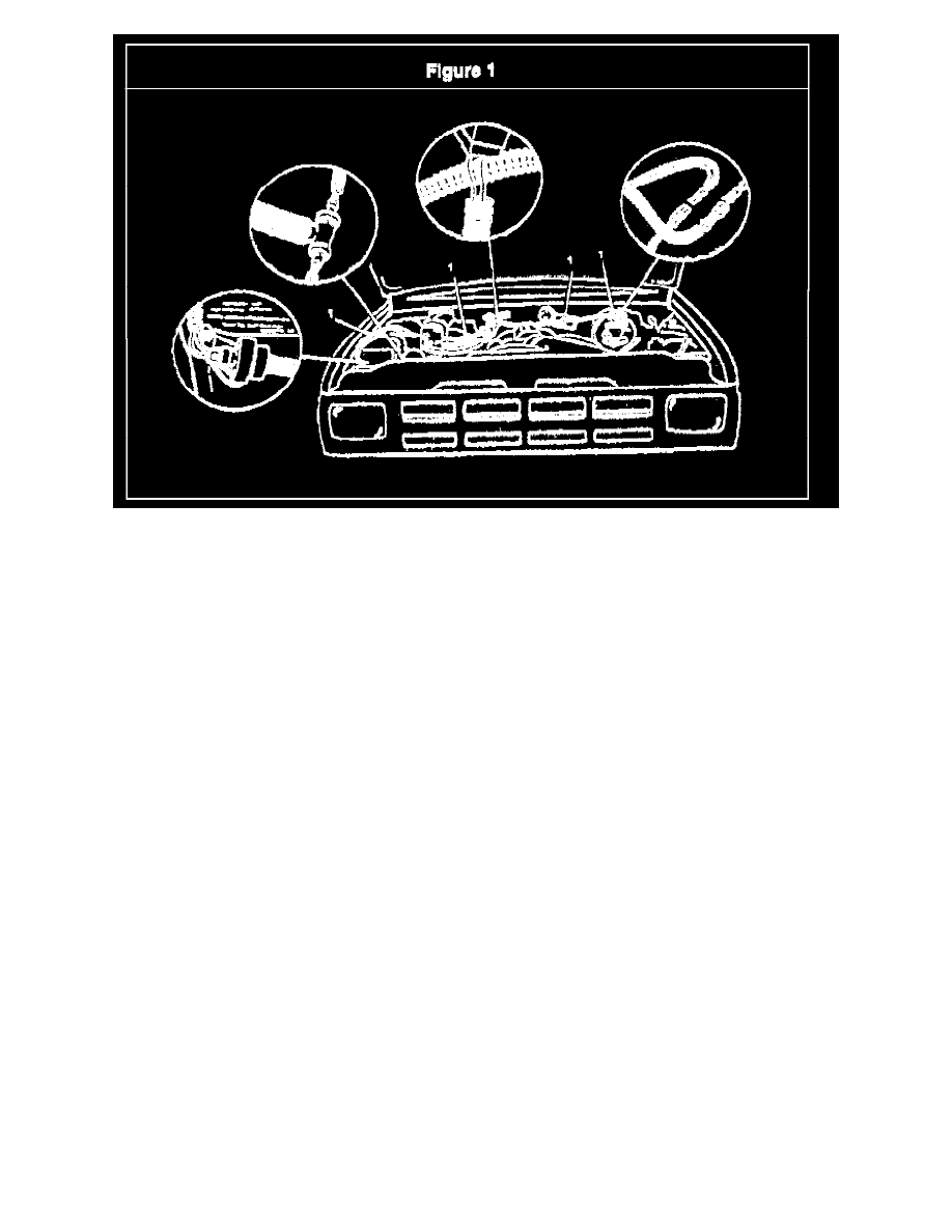
Position the vacuum switch, bracket, and hose assembly as shown in Figure 1 and tighten the bolt to 8 Nm (71 lb in).
5.
Locate the vacuum hose leading from the front axle vacuum actuator, located under the battery tray, to the vacuum switch mounted bon the
transfer case. This vacuum hose typically is routed along the right front frame rail rearward up along the wheel well towards the cowl area of the
engine compartment. On some vehicle this hose may be covered with a black convoluted protective sleeve.
6.
Select a point on the vacuum hose, which was located in the previous step, that will be lower in the vehicle than the new vacuum switch and will
not result in the loading or stretching of either the existing or new hoses when they are connected together.
Important
The location where the vacuum line is tapped into must be lower than the vacuum switch to ensure condensation cannot accumulate in the switch,
possibly resulting in a switch malfunction.
7.
Cut the existing vacuum hose at me point located in the previous step, and connect the ends of the cut vacuum hose to the tee fitting that is part of
the new vacuum switch and hose assembly.
8.
Connect the new wiring harness to the vacuum switch and ensure the locking feature of the connector is engaged.
Important
Ensure that the new harness is routed and secured in such a manner that it will not come in contact with any moving parts or be exposed to any other
conitions that may result in damage to the harness.
9.
Route the new harness is shown in Figure 1 and secure it to the existing Underhood components at the locations indicated (1) using the tie straps
provided in the kit.
10.
Locate and disconnect the existing underhood front exle switch wiring harness connector, located in the area above the brake booster assembly,
and jumper in the new wiring harness.
11.
Raise the vehicle and suitably support.
12.
Loate the transfer case selector switch positioned on top of the transfer case.
13.
Remove any foreign material from around the transfer case selector switch or vacuum connector.
Important
Ensure that the O-ring is removed and discarded.
14.
Disconnect the vacuum connector, remove and discard the transfer case selector switch and the O-ring.