
Silverado 1500 2WD V8-4.8L VIN V (2006)
IMPORTANT: After cutting the damaged terminal from the wire, determine if the remaining wire is long enough to reach the connector without
putting a strain on the wire. If the wire is not long enough, splice a small length of the same gage wire to the existing wire, then crimp the new terminal
on the added wire.
1. Cut the wire as close to the damaged terminal as possible.
2. Strip 5 mm (3/16 in) of insulation from the wire.
3. Depress the spring loaded locator of the crimping tool until the terminal holder is completely visible.
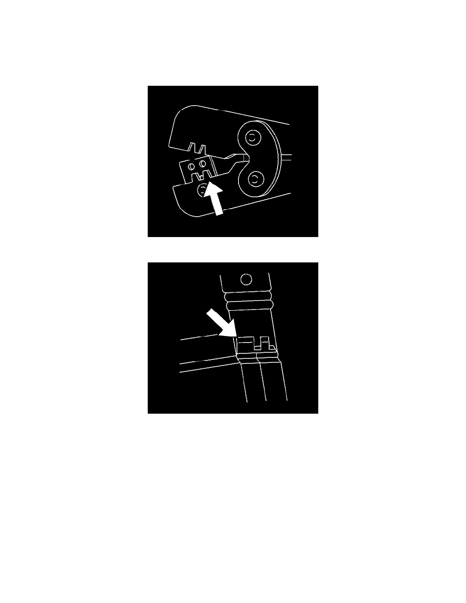
4. Insert terminal into the appropriate terminal holder until it hits bottom and stops. The correct terminal holder is determined by the wire size. Also
ensure that the terminals wings are pointing towards the former on the tool and the release locator.
5. Insert the stripped cable into the terminal. Insulation should be visible on both sides of the terminal insulation wings.
6. Compress the handles until the ratchet automatically releases.
7. Place the terminal into the appropriate cavity and assemble the connector.
Delphi Connectors (Micro-Pack 100W)
DELPHI CONNECTORS (MICRO-PACK 100W)
TOOLS REQUIRED
J-38125 Terminal Repair Kit
TERMINAL REMOVAL PROCEDURE
There are 2 styles of Micro-Pack 100W connectors. These connectors are very similar but use different terminals and have some minor physical
differences also.