
Silverado 1500 2WD V8-6.0L VIN U (2004)
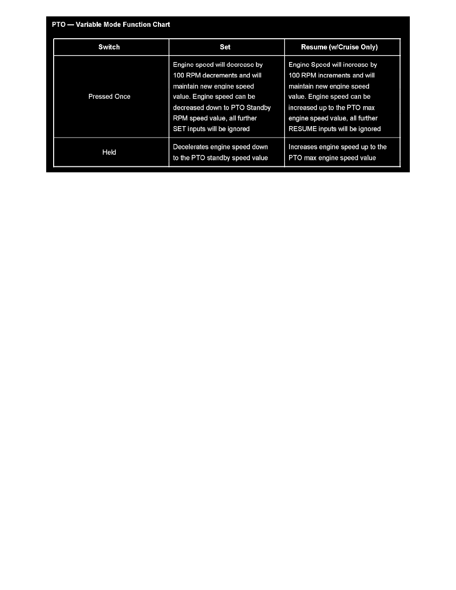
PTO - Variable Mode Function Chart
PTO - Variable Mode Function Chart
PTO COMPONENTS
PTO Switch
The PTO Switch is mounted in the center of the Instrument Panel. The PTO Switch has three positions: OFF, ON and SET. When the PTO switch is
in ON voltage will be present on the PTO On Switch Signal circuit at the relay and the PCM. When the switch is held to the SET position, voltage will
be present on the PTO Engage Signal circuit at the PCM. The PTO indicator light is integral with the switch and will illuminate when the switch is
turned ON. The presence of the indicator being on does not mean that the PTO Solenoid is engaged. The Cruise Control Multi-Function Switch may
be used in conjunction with the PTO Switch. Illumination of the switch is provided through the dimming circuit and controlled in part by internal
switch logic.
Cruise Control Multi-Function Switch
The operation of the PTO system may be through the function control switches located on the multifunction turn signal lever. The cruise control
function control switches includes the ON/OFF, SET/COAST, and R/A. The switch assembly provides driver control of the PTO as well as the cruise
control system. The SET/COAST and R/A switches may be used to increase and decrease engine RPM in increments of 100 RPM. See the chart
below for recommended speeds.
PTO Relay
The PTO Relay is located on the side of the underhood fuse block. The secondary side of the relay is supplied with voltage at all times through the
Fog Lamp fuse. The PTO switch controls the voltage to the primary side of the PTO relay while the PCM controls the ground.
PTO Solenoid
The solenoid is an upfitter supplied part and is replaceable on most PTOs. The PTO solenoid is used on clutch activated PTOs. The PTO relay
supplies the solenoid with voltage when the relay is energized.
PCM
The powertrain control module (PCM) is the control center of the PTO system. Applications with a 6.6L diesel use an ECM. The PCM monitors
numerous engine and vehicle functions. To engage the PTO, the PCM must see the following conditions:
-
PTO switch is ON
-
Engine must be running
-
Transmission must be in PARK or NEUTRAL
-
Park Brake must be set for manual transmission only
-
Vehicle speed must be zero in Preset Mode only
-
Brake or Clutch must not be depressed
The PCM constantly looks at the information from various sensors and other inputs, and controls the systems that affect vehicle performance. The
PCM also performs a diagnostic test on the Electronic Throttle Control system.
TAC Module
The TAC module is the control center for the electronic throttle system. The TAC module and the PCM communicate through a dedicated redundant
serial data circuit. The TAC module and the PCM monitor the commanded throttle position and compare the commanded position to the actual throttle
position. This is accomplished by monitoring the APP and the throttle position (TP) sensor. These 2 values must be within a calibrated value of each
other or a DTC may be set. The TAC module also monitors each individual circuit of the TP sensor and the APP to verify proper operation. The TAC