
Silverado 1500 4WD V8-5.3L VIN B HO (2006)
Brake Rotor/Disc: Testing and Inspection
Brake Rotor Assembled Lateral Runout Correction - Indexing
Brake Rotor Assembled Lateral Runout (LRO) Correction - Indexing
^
Tools Required
-
J 39544-KIT Torque-Limiting Socket Set, or equivalent
-
J 45101-100 Conical Brake Rotor Washers
Caution: Refer to Brake Dust Caution in Service Precautions.
Important:
^
Brake rotor thickness variation MUST be checked BEFORE checking for assembled lateral runout (LRO). Thickness variation exceeding the
maximum acceptable level can cause brake pulsation.
^
Brake rotor assembled lateral runout (LRO) exceeding the maximum allowable specification can cause thickness variation to develop in the brake
rotor over time, usually between 4,800 - 11,300 km (3,000 - 7,000 mi).
1. Remove the J 45101-100 and the lug nuts that were installed during the assembled LRO measurement procedure.
2. Inspect the mating surface of the hub/axle flange and the brake rotor to ensure that there are no foreign particles or debris remaining.
3. Index the brake rotor in a different orientation to the hub/axle flange.
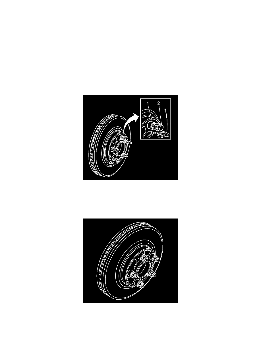
4. Hold the rotor firmly in place against the hub/axle flange and install one of the J 45101-100 (1) and one lug nut (2) onto the upper-most wheel
stud.
5. Continue to hold the rotor secure and tighten the lug nut firmly by hand.
6. Install the remaining J 45101-100 and lug nuts onto the wheel studs and tighten the nuts firmly by hand in a star-pattern.
7. Using the J 39544-KIT, or equivalent, tighten the lug nuts in a star-pattern to specification, in order to properly secure the rotor. Refer to Tire and
Wheel Removal and Installation.
8. Measure the assembled LRO of the brake rotor.