
Silverado 1500 4WD V8-6.0L (2010)
Valve Deactivation Solenoid: Description and Operation
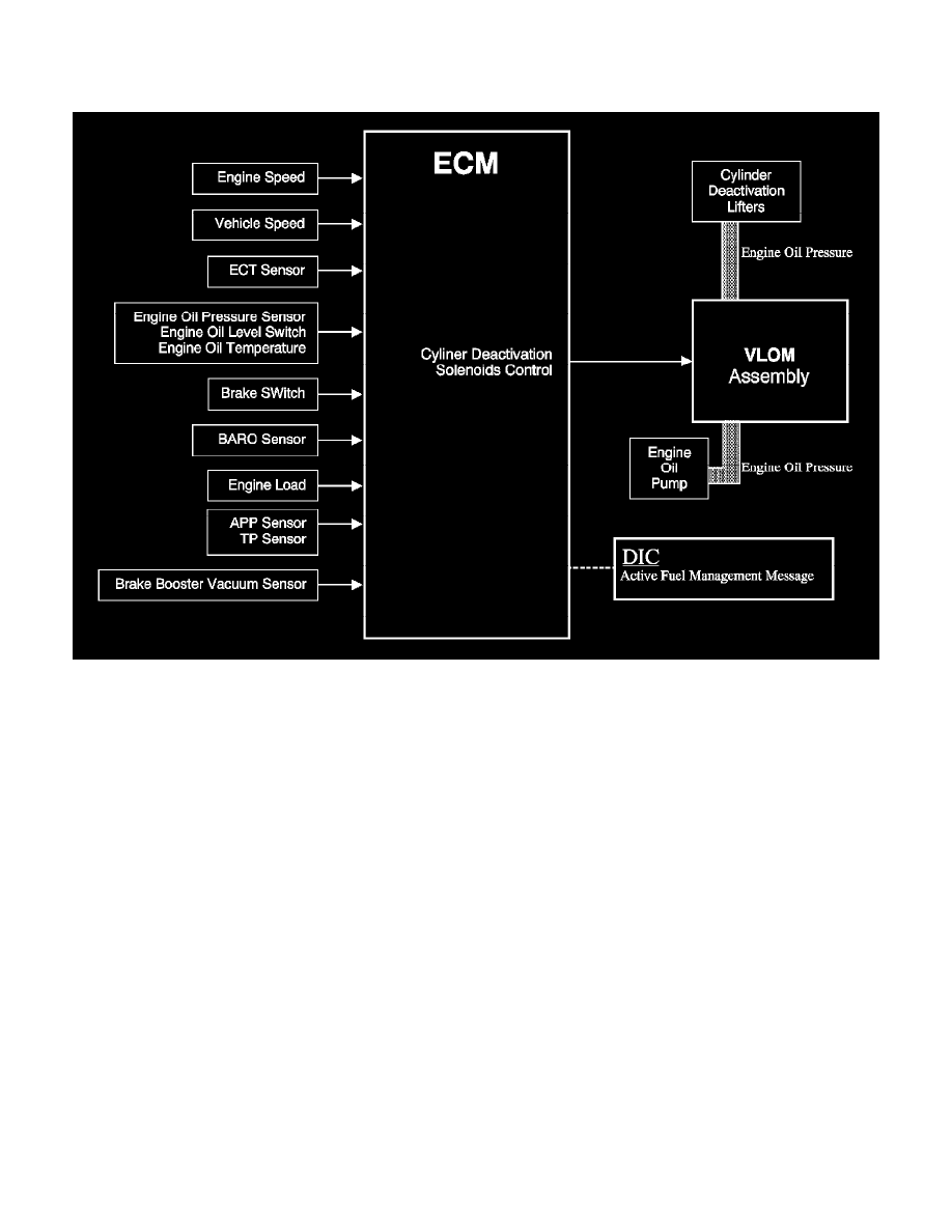
Cylinder Deactivation (Active Fuel Management) System Description
To provide maximum fuel economy under light load driving conditions, the engine control module (ECM) will command the cylinder deactivation
system ON to deactivate engine cylinders 1, 7, 6, and 4, switching to a V4 mode. The engine will operate on 8 cylinders, or V8 mode, during engine
starting, engine idling, and medium to heavy throttle applications.
When cylinder deactivation is commanded, the ECM will determine what cylinder is firing and begin deactivation on the next closest deactivated
cylinder in firing order sequence. For example, if cylinder number 1 is on its combustion event when cylinder deactivation is commanded ON, the next
cylinder in the firing order sequence that can be deactivated is cylinder number 7. If cylinder number 5 is on its combustion event when cylinder
deactivation is commanded ON, then the next cylinder in the firing order sequence that can be deactivated is cylinder number 4.
Cylinder deactivation is accomplished by not allowing the intake and exhaust valves to open on the selected cylinders by using special valve lifters. The
deactivation lifters contain spring loaded locking pins that connect the internal pin housing of the lifter to the outer housing.
The pin housing contains the lifter plunger and pushrod seat which interfaces with the pushrod. The outer housing contacts the camshaft lobe through a
roller. During V8 mode, when all cylinders are active, the locking pins are pushed outward by spring force, locking the pin housing and outer housing
together causing the lifter to function as a normal lifter. When cylinder deactivation is commanded ON, the locking pins are pushed inward with engine
oil pressure directed from the valve lifter oil manifold (VLOM) assembly solenoids. When the lifter pin housing is unlocked from the outer housing, the
pin housing will remain stationary, while the outer housing will move with the profile of the camshaft lobe, which results in the valve remaining closed.
One VLOM solenoid controls both the intake and exhaust valves for each deactivating cylinder. There are 2 distinct oil passages going to each cylinder
deactivation lifter bore, one for the hydraulic lash-adjusting feature of the lifter, and one for controlling the locking pins used for cylinder deactivation.
Although both intake and exhaust valve lifters are controlled by the same solenoid in the VLOM, the intake and exhaust valves do not become
deactivated at the same time. Cylinder deactivation is timed so that the cylinder is on an intake event. During an intake event, the intake cam lobe is
pushing the valve lifter upwards to open the intake valve against the force of the valve spring. The force exerted by the valve spring is acting on the side
of the lifter locking pins, preventing them from moving until the intake valve has closed. When the intake valve lifter reaches the base circle of the
camshaft lobe, the valve spring force is reduced, allowing the locking pins to move, deactivating the intake valve. However, when cylinder deactivation
is commanded ON, the exhaust valve for the deactivated cylinder is in the closed position, allowing the locking pins on the valve lifter to move
immediately, and deactivate the exhaust valve.
By deactivating the exhaust valve first, this allows the capture of a burnt air/fuel charge, or exhaust gas charge, in the combustion chamber. The capture