
Silverado 1500 4WD V8-6.0L Hybrid (2009)
Main Relay (Computer/Fuel System): Testing and Inspection
Powertrain Relay Diagnosis
Diagnostic Instructions
*
Perform theDiagnostic System Check - Vehicle (See: Testing and Inspection/Initial Inspection and Diagnostic Overview/Diagnostic System
Check - Vehicle) prior to using this diagnostic procedure.
*
ReviewStrategy Based Diagnosis (See: Testing and Inspection/Initial Inspection and Diagnostic Overview/Strategy Based Diagnosis) for an
overview of the diagnostic approach.
*
Diagnostic Procedure Instructions (See: Testing and Inspection/Initial Inspection and Diagnostic Overview/Diagnostic Procedure Instructions)
provides an overview of each diagnostic category.
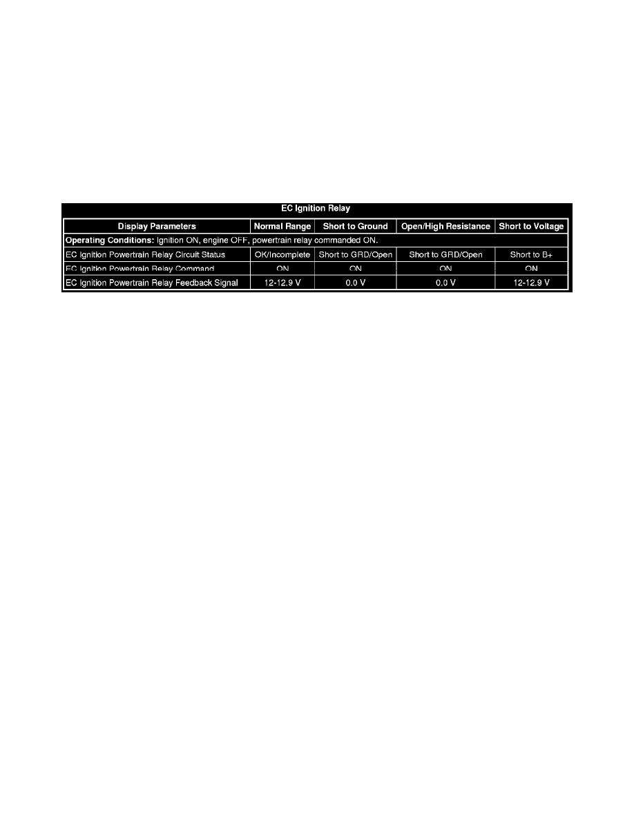
Typical Scan Tool Data
Circuit/System Description
The powertrain relay is a normally open relay. The relay armature is held in the open position by spring tension. Battery positive voltage is supplied
directly to the relay coil and the armature contact at all times. The engine control module (ECM) supplies the ground path to the relay coil control circuit
via an internal integrated circuit called an output driver module (ODM). The ODM output control is configured to operate as a low side driver for the
powertrain relay. The ODM for the powertrain relay also incorporates a fault detection circuit, which is continuously monitored by the ECM. When the
ECM commands the powertrain relay ON, ignition 1 voltage is supplied to the ECM, and to several additional circuits.
Diagnostic Aids
This test procedure requires that the vehicle battery has passed a load test and is completely charged. Refer to Battery Inspection/Test (See: Starting and
Charging/Testing and Inspection/Component Tests and General Diagnostics/Battery Inspection/Test) .
Reference Information
Schematic Reference
Engine Controls Schematics (See: Diagrams/Electrical Diagrams)
Connector End View Reference
Component Connector End Views (See: Diagrams/Connector Views)
Electrical Information Reference
*
Circuit Testing (See: Testing and Inspection/Component Tests and General Diagnostics)
*
Connector Repairs (See: Testing and Inspection/Component Tests and General Diagnostics)
*
Testing for Intermittent Conditions and Poor Connections (See: Testing and Inspection/Component Tests and General Diagnostics)
*
Wiring Repairs (See: Testing and Inspection/Component Tests and General Diagnostics)
Scan Tool Reference
Control Module References (See: Testing and Inspection/Programming and Relearning) for scan tool information
Special Tools
*
J 35616 GM-Approved Terminal Test Kit
*
J 43244 Relay Puller Pliers
Circuit/System Verification
1. Ignition OFF, open the hood to disable the Auto-Stop function. Refer to Hybrid Modes of Operation Description (See: Hybrid Drive
Systems/Description and Operation/Hybrid Controls/Hybrid Modes of Operation Description) .
2. Ignition ON, verify the scan tool hood position parameter displays Open.
‹› If the hood position does not display Open, refer toDiagnostic Trouble Code (DTC) List - Vehicle (See: Testing and Inspection/Diagnostic