
Silverado 1500 4WD V8-6.2L (2010)
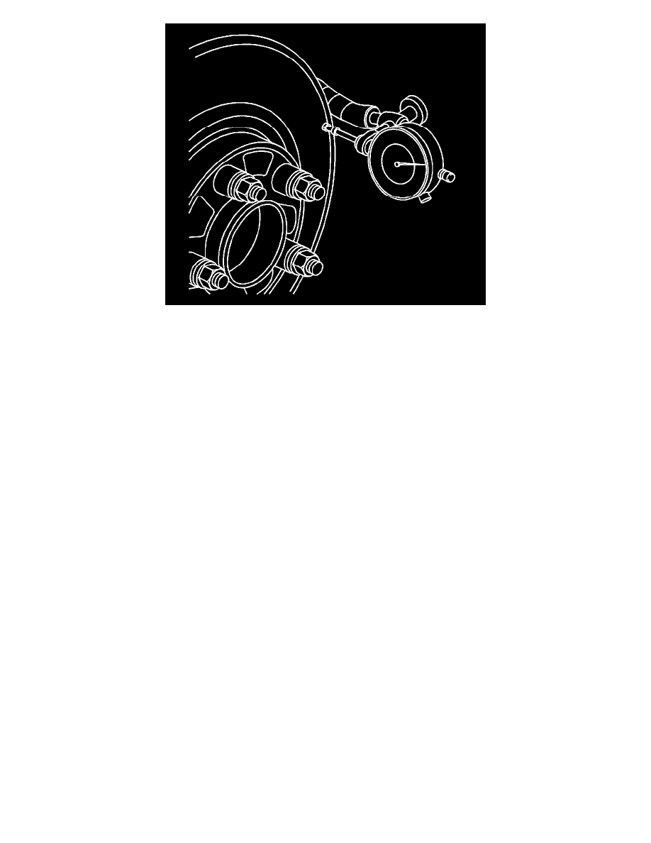
10. Mount a dial indicator, J-45101 - Hub
and Wheel Runout Gauge , or equivalent, to the steering knuckle and position the indicator button so it contacts the brake rotor friction surface at a 90
degree angle, approximately 13 mm (0.5 in) from the outer edge of the rotor.
11. Measure and record the assembled LRO of the brake rotor.
1. Rotate the rotor until the lowest reading is displayed on the indicator dial, then set the dial to zero.
2. Rotate the rotor until the highest reading is displayed on the dial.
3. Mark the location of the high spot relative to the nearest wheel stud, or studs.
4. Measure and record the amount of LRO.
12. Compare the brake rotor assembled LRO to the following specifications:
Brake rotor maximum allowable assembled lateral runout: 0.05 mm (0.002 in)
Brake rotor maximum allowable assembled lateral runout: 0.05 mm (0.002 in)
Brake rotor maximum allowable assembled lateral runout: 0.05 mm (0.002 in)
13. If the brake rotor assembled LRO is within specifications, proceed to step 18.
If the brake rotor assembled LRO exceeds the specification, refinish the rotor to ensure true parallelism, refer to Brake Rotor Refinishing (See:
Brake Rotor Refinishing). After refinishing the rotor, proceed to step 14.
14. Mount a dial indicator, J-45101 - Hub and Wheel Runout Gauge , or equivalent, to the steering knuckle and position the indicator button so it
contacts the brake rotor friction surface at a 90 degree angle, approximately 13 mm (0.5 in) from the outer edge of the rotor.
15. Measure and record the assembled LRO of the brake rotor.
1. Rotate the rotor until the lowest reading is displayed on the indicator dial, then set the dial to zero.
2. Rotate the rotor until the highest reading is displayed on the dial.
3. Mark the location of the high spot relative to the nearest wheel stud, or studs.
4. Measure and record the amount of LRO.
16. Compare the brake rotor assembled LRO to the following specification:
Brake rotor maximum allowable assembled lateral runout: 0.05 mm (0.002 in)
Brake rotor maximum allowable assembled lateral runout: 0.13 mm (0.005 in)
17. If the brake rotor assembled LRO measurement exceeds the specification, bring the LRO to within specifications. Refer to Brake Rotor Assembled
Lateral Runout Correction (See: Brake Rotor Assembled Lateral Runout Correction).
18. If the brake rotor assembled LRO measurement is within specification, install the brake caliper and depress the brake pedal several times to secure
the rotor in place before removing the J-45101-100 - Conical Brake Rotor Washers and the lug nuts.