
Silverado 2500 4WD V8-6.6L DSL Turbo (2010)
Cruise Control: Testing and Inspection
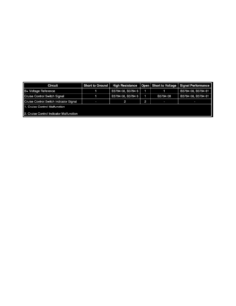
Cruise Control Indicator Malfunction (Switch Indicator Malfunction)
Cruise Control Indicator Malfunction (Switch Indicator Malfunction)
Diagnostic Instructions
*
Perform the Diagnostic System Check - Vehicle (See: Testing and Inspection/Initial Inspection and Diagnostic Overview/Diagnostic System
Check - Vehicle) prior to using this diagnostic procedure.
*
Review Strategy Based Diagnosis (See: Testing and Inspection/Initial Inspection and Diagnostic Overview/Strategy Based Diagnosis) for an
overview of the diagnostic approach.
*
Diagnostic Procedure Instructions (See: Testing and Inspection/Initial Inspection and Diagnostic Overview/Diagnostic Procedure Instructions)
provides an overview of each diagnostic category.
Diagnostic Fault Information
Circuit/System Description
The cruise control switch contains an LED that illuminates to indicate the cruise control system has been switched ON. Voltage is applied through the
ON/OFF switch to the LED when the switch is pressed. The BCM provides the ground path for the LED through a dedicated control circuit. Pressing the
switch again opens the switch and the lamp turns OFF.
Reference Information
Schematic Reference
Cruise Control Schematics (See: Diagrams/Electrical Diagrams)
Connector End View Reference
Component Connector End Views (See: Diagrams/Connector Views)
Description and Operation
*
Cruise Control Description and Operation (See: Description and Operation)
*
Indicator/Warning Message Description and Operation (See: Instrument Panel, Gauges and Warning Indicators/Description and
Operation/Indicator/Warning Message)
Electrical Information Reference
*
Circuit Testing (See: Testing and Inspection/Component Tests and General Diagnostics/General Electrical Diagnostic Procedures/Circuit
Testing/Circuit Testing)
*
Connector Repairs (See: Testing and Inspection/Component Tests and General Diagnostics/General Electrical Diagnostic Procedures/Connector
Repairs/Connector Repairs)
*
Testing for Intermittent Conditions and Poor Connections (See: Testing and Inspection/Component Tests and General Diagnostics/General
Electrical Diagnostic Procedures/Circuit Testing/Testing for Intermittent Conditions and Poor Connections)
*
Wiring Repairs (See: Testing and Inspection/Component Tests and General Diagnostics/General Electrical Diagnostic Procedures/Wiring
Repairs/Wiring Repairs)
Scan Tool Reference
Control Module References (See: Testing and Inspection/Programming and Relearning) for scan tool information
Circuit/System Verification
Ignition ON, observe the cruise control indicator while applying the cruise On/Off switch. The indicator should turn on and off accordingly with the
applied switch.
Circuit/System Testing