
Silverado 2500 4WD V8-8.1L VIN G (2006)
Electronic Throttle Actuator: Description and Operation
THROTTLE ACTUATOR CONTROL (TAC) SYSTEM DESCRIPTION
The throttle actuator control (TAC) system uses vehicle electronics and components to calculate and control the position of the throttle blade. This
eliminates the need for a mechanical cable attachment from the accelerator pedal to the throttle body. This system also performs the cruise control
functions as well.
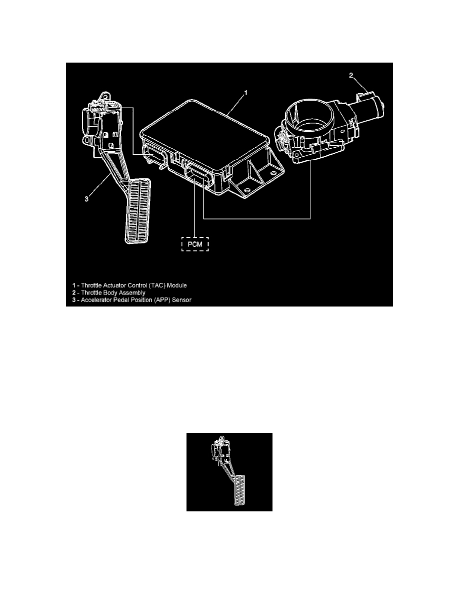
The TAC system components include the following:
-
The accelerator pedal position (APP) sensor
-
The throttle body
-
The throttle actuator control (TAC) module
-
The powertrain control module (PCM)
Each of these components interface together to ensure accurate calculations and control of the throttle position.
Accelerator Pedal Position (APP) Sensor
The APP sensor is mounted on the accelerator pedal assembly. The APP is actually 3 individual accelerator pedal position sensors within one housing.
Three separate signal, low reference, and 5.0-volt reference circuits are used to connect the APP and the TAC module. The APP sensor 1 voltage
should increase as the accelerator pedal is depressed, from below 1.0 volt at 0 percent pedal travel to above 2.0 volts at 100 percent pedal travel.
APP sensor 2 voltage should decrease from above 4.0 volts at 0 percent pedal travel to below 2.9 volts at 100 percent pedal travel. APP sensor 3
voltage should decrease from above 3.8 volts at 0 percent pedal travel to below 3.1 volts at 100 percent pedal travel.