
Silverado 2500 4WD V8-8.1L VIN G (2006)
Clutch Pedal Assembly: Service and Repair
Clutch Pedal Replacement
Removal Procedure
Caution: Unless directed otherwise, the ignition and start switch must be in the OFF or LOCK position, and all electrical loads must be OFF
before servicing any electrical component. Disconnect the negative battery cable to prevent an electrical spark should a tool or equipment come in
contact with an exposed electrical terminal. Failure to follow these precautions may result in personal injury and/or damage to the vehicle or its
components.
For Vehicles equipped with OnStar (UE1) with Back Up Battery:
The Back Up Battery is a redundant power supply to allow limited OnStar functionality in the event of a main vehicle battery power disruption to
the VCIM (OnStar module). Do not disconnect the main vehicle battery or remove the OnStar fuse with the ignition key in any position other than
OFF. Retained accessory power (RAP) should be allowed to time out or be disabled (simply opening the driver door should disable RAP) before
disconnecting power. Disconnecting power to the OnStar module in any way while the ignition is On or with RAP activated may cause activation
of the OnStar Back-Up Battery (BUB) system and will discharge and permanently damage the back-up battery. Once the Back-Up Battery is
activated it will stay on until it has completely discharged. The BUB is not rechargeable and once activated the BUB must be replaced.
1. Disconnect the negative battery cable.
2. Disable the SIR system. Refer to SIR Disabling and Enabling in SIR. See: Body and Frame/Interior Moulding / Trim/Dashboard / Instrument
Panel/Air Bag(s) Arming and Disarming
3. Remove the instrument panel (I/P) cluster trim bezel. Refer to Instrument Panel Cluster Trim Plate Bezel Replacement in Instrument Panel,
Gauge., and Console. See: Instrument Panel, Gauges and Warning Indicators/Instrument Cluster / Carrier/Service and Repair
4. Remove the driver side knee bolster and deflector. Refer to Knee Bolster Replacement in Instrument Panel, Gauge., and Console.
5. Remove the left and right I/P end trim panels.
6. Remove the park brake release lever from the I/P. Refer to Parking Brake Release Handle Assembly Replacement in Park Brake. See: Brakes and
Traction Control/Parking Brake System/Parking Brake Lever/Service and Repair
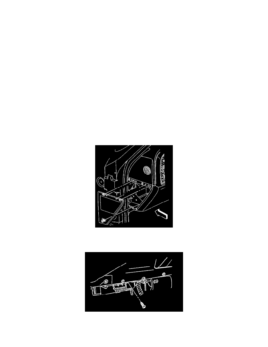
7. Remove the data link connector fastener and position aside.