
Silverado 3500 2WD V8-6.6L DSL Turbo VIN 2 (2004)
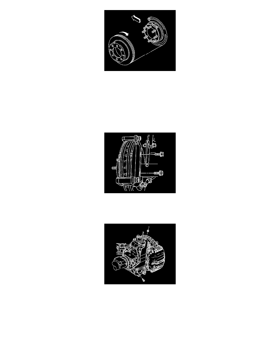
5. Install the rotor by slowly turning the rotor while pushing the rotor towards the axle.
6. If the brake rotor was removed and installed as part of a brake system repair, measure the assembled lateral runout (LRO) of the brake rotor to
ensure optimum performance of the disc brakes. Refer to Brake Rotor Assembled Lateral Runout (LRO) Measurement.
7. If the brake rotor assembled LRO measurement exceeds the specification, bring the LRO to within specifications. Refer to Brake Rotor Assembled
Lateral Runout (LRO) Correction.
8. Install the brake caliper and the brake caliper mounting bracket as an assembly to the vehicle.
9. Perform the following procedure before installing the 2 brake caliper bracket mounting bolts.
1. Remove all traces of the original adhesive patch.
2. Clean the threads of the bolts with brake parts cleaner or the equivalent and allow to dry.
3. Apply Threadlocker GM P/N 12345493 (Canadian P/N 10953488) to the threads of the bolts.
10. Notice:
Refer to Fastener Notice in Service Precautions.
Install the brake caliper bracket mounting bolts.
^
Tighten the brake caliper bracket mounting bolts to 200 Nm (148 ft. lbs.).
11. Install the quarter shaft shield.
12. Install the quarter shaft shield nut and the bolt.
^
Tighten the quarter shaft shield nut and the bolt to 25 Nm (18 ft. lbs.).
13. Install the tire and wheel assembly.
14. Lower the vehicle.
15. With the engine OFF gradually apply the brake pedal to approximately 2/3 of it's travel distance.
16. Slowly release the brake pedal.
17. Wait 15 seconds then repeat steps 15-16 until a firm pedal is obtained. This will properly seat the brake caliper pistons and brake pads.