
Silverado 3500 2WD V8-6.6L DSL Turbo VIN 2 (2004)
4. Insert the Weather Pack(R) terminal removal tool into the front (mating end) of the connector cavity until it rests on the cavity shoulder (1).
5. Gently pull on the wire to remove the terminal through the back of the connector (2).
IMPORTANT: Never use force to remove a terminal from a connector.
6. Inspect the terminal and connector for damage.
7. Reform the lock tang (2) and reset terminal in connector body.
8. Close secondary locks and join connector halves.
9. Verify that circuit is complete and working satisfactorily.
10. Perform system check.
Micro-Pack 100W Connectors
MICRO-PACK 100W CONNECTORS
TOOLS REQUIRED
J 38125-D Terminal Repair Kit
REMOVAL PROCEDURE
There are 2 styles of Micro-Pack 100W connectors. These connectors are very similar but use different terminals and have some minor physical
differences also.
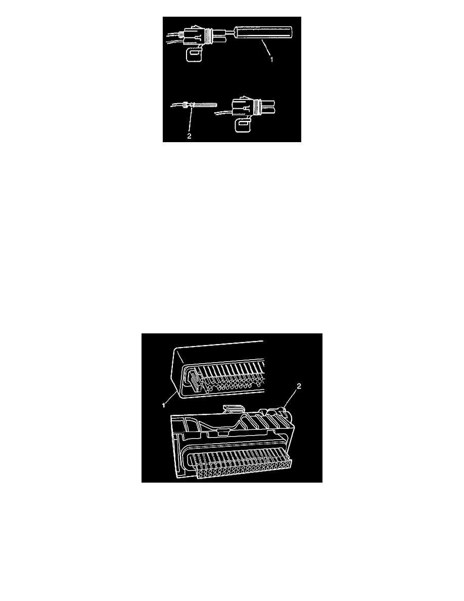
The first connector design of the Micro-Pack 100W (1) has a white connector interface that holds the terminals. The second design of the Micro-Pack
100W (2)has a gray interface to hold the terminals. Also, the first design has terminal cavities that are further apart (3 mm centerline) and offset from
the other row of terminal cavities in the connector. The second design has terminals cavities that are closer together (2.54 mm centerline) and aligned
vertically. One other way to identify the second design is the thin strip of material that runs along the outside of the cavities.
IMPORTANT: There are 2 styles of Micro-Pack 100W terminals which are very similar. Ensure that you have the correct terminal before crimping
the new terminal to the wire. The first design connector uses the longer terminal (1) that has a raised area in front of the recess in the terminal. The
second design connector uses the shorter terminal without the raised area.