
Silverado 3500 2WD V8-6.6L DSL Turbo VIN 2 (2004)
Power Take-Off: Symptom Related Diagnostic Procedures
- Symptoms - Power Take-Off (PTO)
SYMPTOMS - POWER TAKE-OFF (PTO)
IMPORTANT: The following steps must be completed before using the symptom tables.
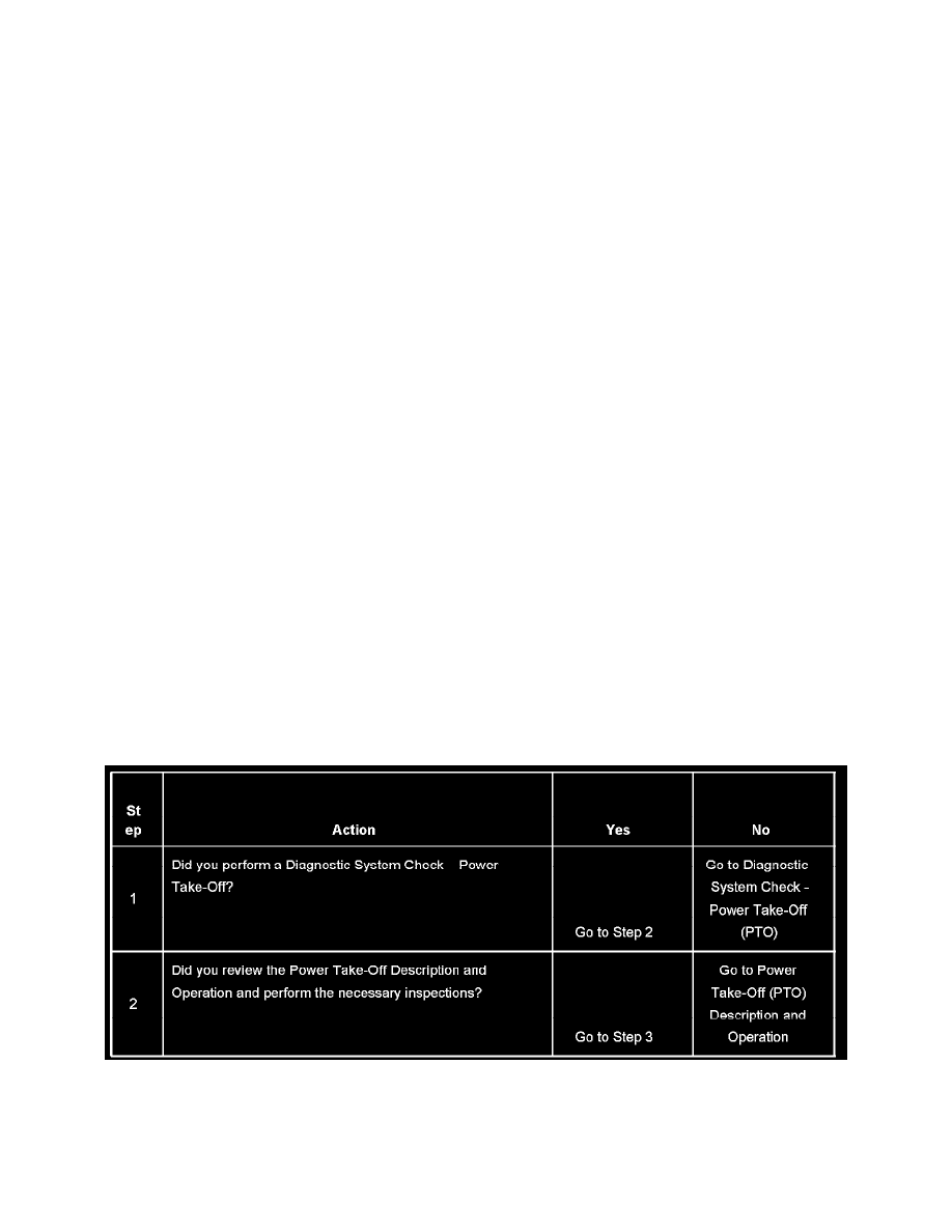
1. Perform the Diagnostic System Check - Power Take-Off (PTO) before using the Symptom Tables in order to verify that all of the following are
true:
-
There are no PCM or TAC module DTCs set.
-
The PCM and TAC module can communicate to each other via the serial data links.
2. Review the system operation in order to familiarize yourself with the system functions. Refer to Power Take-Off (PTO) Description and
Operation.
VISUAL/PHYSICAL INSPECTION
-
Inspect the upfitter connections of the PTO system.
-
Inspect the easily accessible, or the visible system components for obvious damage or conditions which could cause the symptom.
-
Inspect the transmission and the hydraulic pump for the proper fluid level.
INTERMITTENT
Faulty electrical connections or wiring may be the cause of intermittent conditions.
SYMPTOM LIST
Refer to a symptom diagnostic procedure from the following list in order to diagnose the symptom:
-
Power Take-Off (PTO) Does Not Engage
-
Engine RPM Does Not Increase with Power Take-Off Engaged
-
Power Take-Off (PTO) Indicator Inoperative
Engine RPM Does Not Increase With Power Take-Off Engaged
ENGINE RPM DOES NOT INCREASE WITH POWER TAKE-OFF ENGAGED
CIRCUIT DESCRIPTION
When the Power Take-Off (PTO) switch is turned to the ON position and all PTO engage conditions are met, the engine RPM should increase to the
standby speed. When the Powertrain Control Module (PCM) receives the signal from the PTO switch the PCM will send a signal to the Throttle
Actuator Control Module (TAC). The TAC module controls the TAC motor which changes the position of the throttle. Communications between the
two modules is monitored and checked for accuracy by the PCM. DTCs may be recorded in the event of the failure. The 6.6L diesel engine does not
have a TAC system and the engine RPM is strictly controlled by the ECM and the Fuel Injection Control Module.
TEST DESCRIPTION
Steps 1-2