
Silverado 3500 4WD V8-6.0L VIN U (2004)
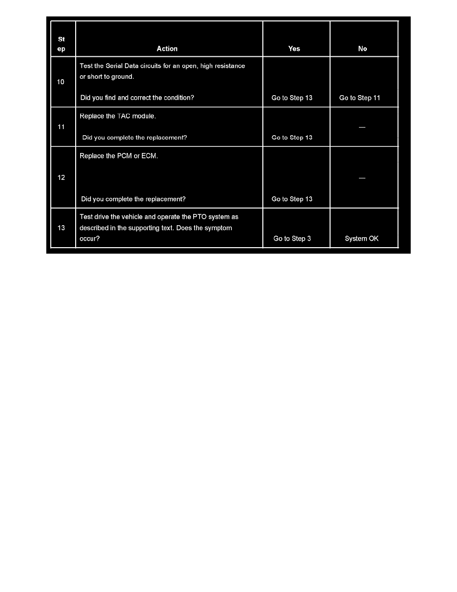
Steps 10-13
The numbers below refer to the step numbers on the diagnostic table.
3. This step checks for other system DTCs that may affect the PTO.
6. This step tests the PCM for the PTO Enable signal.
7. This step tests the communication between the PCM and the TAC module.
8. This step tests the PTO On Switch Signal circuit.
9. This step tests the PTO On Switch-Signal circuit for an open, high resistance or short to ground.
10. This step tests the Serial Data circuits for an open, high resistance or short to ground.
Power Take-Off (PTO) Does Not Engage
POWER TAKE-OFF (PTO) DOES NOT ENGAGE
CIRCUIT DESCRIPTION
This symptom table aids in the diagnosis of a failed power take-off (PTO) solenoid engagement. This diagnostic does not expose a mechanical
condition with the PTO itself. Voltage is supplied at all times through the cruise fuse to the secondary side of the relay. When the relay is energized,
the contacts close and current is allowed to flow to the PTO solenoid. The solenoid has its own external ground. When the ignition switch is in the
RUN position, voltage is present at the PTO switch. When the PTO switch is in the ON position, voltage is present at the coil of the relay and at the
PCM. If the PCM sees all of the conditions necessary to engage the solenoid, the PCM grounds the primary circuit of the relay.
TEST DESCRIPTION