
Silverado Classic 1500 2WD V8-6.0L (2007)
4. Important: If the rotor was removed using the jack screw method you must ensure that the hub flange is free of nicks or marks caused by this
procedure. Remove all raised nicks or marks before installing the rotor.
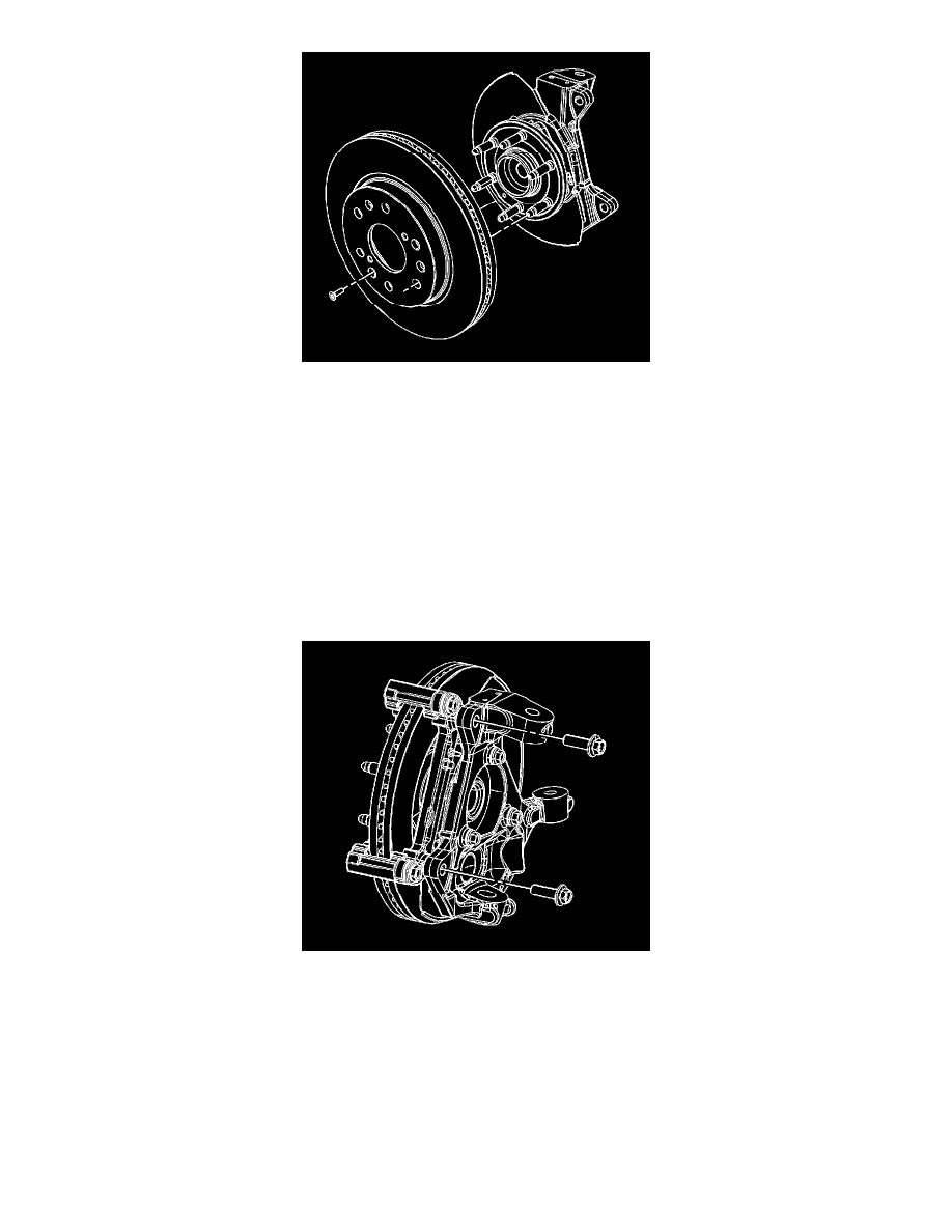
Align the rotor to its original position on the hub (if applicable) and install the rotor.
5. Notice: Refer to Fastener Notice in Service Precautions.
Install the brake rotor screw.
Tighten the screw to 12 Nm (106 inch lbs.).
6. If the rotor was removed and installed as part of a brake system repair, measure the assembled lateral runout (LRO) of the rotor to ensure optimum
performance of the disc brakes. Refer to Brake Rotor Assembled Lateral Runout Measurement. See: Testing and Inspection/Brake Rotor
Assembled Lateral Runout Measurement
7. If the rotor assembled LRO measurement exceeds the specification, bring the LRO to within specifications. Refer to Brake Rotor Assembled
Lateral Runout Correction. See: Testing and Inspection/Brake Rotor Assembled Lateral Runout Correction
8. Install the caliper and caliper bracket as a assembly.
9. Perform the following procedure before installing the caliper bracket bolts.
1. Remove all traces of the original adhesive patch.
2. Clean the threads of the bolt with brake parts cleaner or the equivalent and allow to dry.
3. Apply Threadlocker GM P/N 12345493 (Canadian P/N 10953488) to the threads of the bolt.
10. Install the brake caliper bracket bolts.
Tighten the bolts to 180 Nm (133 ft. lbs.).
11. Install the tire and wheel assembly.
12. Lower the vehicle.
13. With the engine OFF, gradually apply the brake pedal to approximately 2/3 of its travel distance.
14. Slowly release the brake pedal.
15. Wait 15 seconds, then repeat steps 13-14 until a firm pedal is obtained. This will properly seat the caliper pistons and pads.