
Silverado Classic 2500 2WD V8-8.1L (2007)
2. Using moderate pressure, apply the non-directional finish:
^
If the lathe is equipped with a non-directional finishing tool, apply the finish with 120-grit aluminum oxide sandpaper.
^
If the lathe is not equipped with a non-directional finishing tool, apply the finish with a sanding block and 150-grit aluminum oxide
sandpaper.
3. After applying a non-directional finish, clean each friction surface of the brake rotor with denatured alcohol, or an equivalent approved brake
cleaner.
9. Remove the lathe from the vehicle.
10. Measure the assembled LRO of the brake rotor. Refer to Brake Rotor Assembled Lateral Runout Measurement. See: Brake Rotor Assembled
Lateral Runout Correction
11. If the brake rotor assembled LRO measurement still exceeds the maximum allowable specification, refer to Brake Rotor Assembled Lateral
Runout Correction. See: Brake Rotor Assembled Lateral Runout Correction
12. If the brake rotor assembled LRO is within specification, install the brake caliper and depress the brake pedal several times to secure the rotor in
place before removing the J 45101-100 and the lug nuts.
Brake Rotor Assembled Lateral Runout Measurement
Brake Rotor Assembled Lateral Runout Measurement
Tools Required
^
J 39544-KIT Torque-Limiting Socket Set, or equivalent
^
J 41013 Rotor Resurfacing Kit
^
J 42450-A Wheel Hub Resurfacing Kit
^
J 45101 Hub and Wheel Runout Gage
^
J 45101-100 Conical Brake Rotor Washers
Caution: Refer to Brake Dust Caution.
Important:
^
Brake rotor assembled lateral runout (LRO) exceeding the maximum allowable specification can cause thickness variation to develop in the brake
rotor over time, usually between 4,800 - 11,300 km (3,000 - 7,000 mi).
^
Brake rotor thickness variation MUST be checked BEFORE checking for assembled lateral runout (LRO). Thickness variation exceeding the
maximum acceptable level can cause brake pulsation. Refer to Brake Rotor Thickness Variation Measurement. See: Brake Rotor Thickness
Variation Measurement
1. Matchmark the position of the brake rotor to the wheel studs if this has not been done already.
2. Important: Whenever the brake rotor has been separated from the hub/axle flange, any rust or contaminants should be cleaned from the hub/axle
flange and the brake rotor mating surfaces. Failure to do this may result in excessive assembled lateral runout (LRO) of the brake rotor, which
could lead to brake pulsation.
Inspect the mating surface of the hub/axle flange and the brake rotor to ensure that there are no foreign particles, corrosion, rust, or debris
remaining. If the wheel hub/axle flange and/or if the brake rotor mating surfaces exhibit these conditions, perform the following steps:
1. Remove the brake rotor.
2. Using the J 42450-A, thoroughly clean any rust or corrosion from the mating surface of the hub/axle flange.
3. Using the J 41013, thoroughly clean any rust or corrosion from the mating surface of the brake rotor.
4. Clean the friction surfaces of the brake rotor with denatured alcohol, or an equivalent approved brake cleaner.
3. Install the rotor to the hub/axle flange using the matchmark made prior to removal.
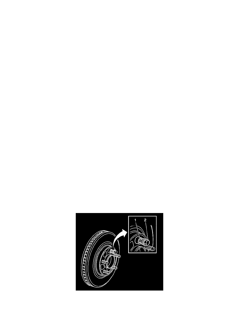
4. Hold the rotor firmly in place against the hub/axle flange and install one of the J 45101-100 (1), and one lug nut (2) onto the upper-most wheel